Adding a Depth Camera
Hi everyone, today we’re going to kick things up a notch by moving into another dimension. That’s right, we’re going 3D!
We’re going to be looking at depth cameras, which are like regular cameras except they can see in 3D which I think is really cool. This video assumes you’ve already seen the last one on regular cameras, so if you haven’t seen that one, pause this one and watch it and come back.
And just like the last tutorial it’ll be split into four sections so you can jump straight to where you need. So we’ll see:
-
What depth cameras are
-
How they’re used in ROS
-
How to simulate one in Gazebo
-
And then we’ll connect to an actual depth camera we can use on our robot
-
What are depth cameras?
-
How are they used in ROS?
-
Simulation
-
Real one
Now some of you will be watching this as part of my series on building a mobile robot with ROS - link to the playlist is in the description - and you’re thinking “I just got a Pi camera for the last video, now I need a depth camera too?”.
I don’t recommend getting both, the rest of the series will mostly be using just the RGB data from the camera, not the depth data, I just wanted to cover depth cameras because some people might want to use a depth camera from the beginning, to have flexibility to do different things with it down the track.
What are depth cameras?
Put simply, depth cameras are cameras that return a distance or depth to each pixel - this can be instead of or in addition to the intensity which is what we get in a normal camera (which we saw in the last tutorial).
The technologies used to produce this “depth image”, but some common ones are:
- Structured light (Kinect v1) which broadcasts an infrared pattern and then uses a camera to see how the light is distorted
- Time-of-Flight (Kinect v2) which is kind of like a lidar in that it uses pulses of light and measures how long they take to come back
- Stereo (OAK-D Lite) - this is like our own eyes, it uses two cameras, slightly separated, and figures out the depth based on the distance between them.
Regardless of the method, software either on-board the camera or on the computer can process the raw output to generate a depth image, and then that depth image can be converted into a point cloud, very similar to 3D lidar. This technology is getting better and better, and modern machine learning techniques can produce very good depth images, sometimes even just from RGB data.
Even more so than regular cameras, it’s important that depth cameras are calibrated properly so that the final points are in the correct location in space.
There are more and more algorithms out there that can make use of depth cameras, because two of the main things we do with cameras - object detection and SLAM - can really benefit from having the depth information.
How are they used in ROS
For the most part, depth cameras are the same as their regular counterparts. They have a driver of some sort, that publishes an Image topic and a CameraInfo topic, and they can use image_transport to handle compression and so on.
The difference is in the content of the image data. Each pixel is stored as a 32-bit float or sometimes as a 16-bit unsigned integer. If it’s a float, the values represent metres, and if it’s an int then they are millimeters. You can check out the ROS Standard REP 118 for more on this.
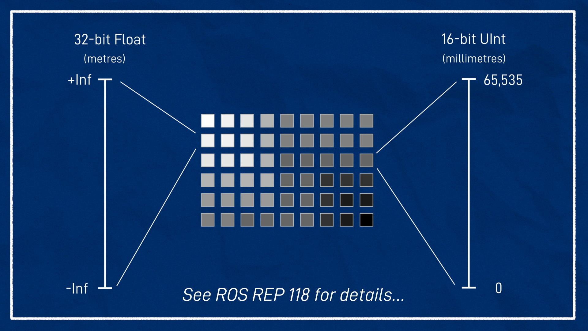
You can view these images too, and visually “see” the depth. It’s worth noting that when you’re looking at them you probably want the image to be “normalised”. This is where it scales the brightness by taking the furthest thing that’s actually visible and making it white, and the closest thing black, so that you can actually see everything.
ROS also provides the depth_image_proc package for working with depth images. This lets us do things like converting int depth images to float, converting depth images to point clouds, and aligning depth images with RGB images, which is called registration.
Simulation
Now we’re going to look at how to simulate a depth camera in Gazebo. Note that this is going to rely heavily on the previous tutorial (on regular cameras) so make sure you’ve done it first.
To avoid breaking our existing camera simulation, let’s duplicate camera.xacro and name the new one depth_camera.xacro. Then, we want to open up robot.urdf.xacro, duplicate the appropriate include line, and comment out the old one. We can now make our changes to the new file.
We’ll go down to the <sensor> tag and change the type from "camera" to "depth", and that’s just about it!
<sensor name="camera" type="depth">
    ...
</sensor>
Now we can rerun the Gazebo simulation launch script, just like the previous tutorials. It should now be simulating the depth camera.
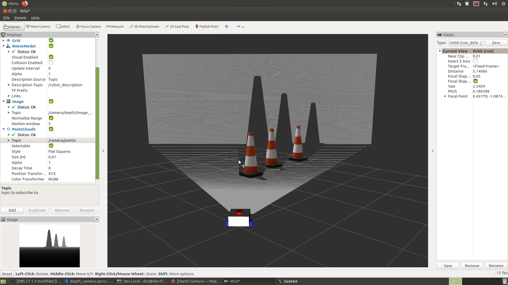
We can open up RViz like usual.
Now if we add an Image display and drop down the topic list, we can see that inside the /camera namespace it’s created a /depth namespace. And then in the depth namespace we’ve got all the normal camera things, image_raw, camera_info and so on. So we can select the depth image, and it looks like it hasn’t worked, it’s just a black rectangle, clicking these doesn’t do anything, but we’ll come back to that in a minute.
One little thing you might notice is we’ve lost our little preview, I don’t know if that’s a bug or deliberate, but it happens
Instead, we can also add a PointCloud2 display. Then we can select /camera/points from the dropdown and you’ll see it’s selected the RGB8 colour transformer automatically so that we get coloured points. And over in the 3D view we see that we’ve definitely got depth working, we can move the camera around and see the pixels in 3D.
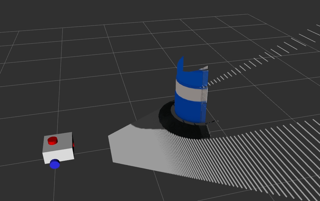
But there’s an obvious issue here - our cones are blue. So let’s go fix that and the black image.
You’ll notice here that it says RGB8, but because of endianness, it’s actually sort of BGR. So if we go back into our file, we can swap R8G8B8 for B8G8R8 swapping red and blue, and it really should be able to detect all that automatically but it doesn’t.
To fix the depth image thing we’re going to add a couple of parameters down here in the plugin, min_depth and max_depth. To be honest I don’t understand 100% what these are doing, I think it’s the clipping planes up here that actually determine the min and max depth. So I’m just going to set these to 0.1 and 100 . Now let’s close Gazebo and rerun it.
Hit Reset in Rviz, and we can see now our depth image is there, it looks like a normal greyscale image except the pixel colour represents the depth, and our 3D view is the right colour. (note normalize)
Using teleop_twist_keyboard like normal, we should be able to drive our robot around and explore our scene in 3D.
Note, there appears to be a synchronisation issue with the colours and the points, I think this is internal to Gazebo itself or the Gazebo-ROS plugin. I don’t know if there’s a way to fix it, but if you do please tell me!
Real One
Now that we’ve got it going in simulation, let’s connect to a real depth camera….
Note that in terms of this mobile robot tutorial series, I don’t plan to make use of the the depth aspect of the camera, but I wanted to chat about it because I’m sure some people will want to, and having the depth data as well as RGB opens up more flexibility.
For this demo I’ll be using the OAK-D Lite, which is sold by a company called Luxonis (find out how to pronounce) as part of their DepthAI platform. It’s also connected to OpenCV - OAK-D stands for OpenCV AI Kit - Depth.
It’s got an RGB camera in the middle, and two greyscale cameras on the side, which can be used for depth estimation. It also has an Intel Movidius Vision Processing Unit on board, which means you can set it up to execute code on board, like facial recognition, which saves some compute power on the machine it’s connected to - especially handy with a Raspberry Pi.
I picked up this camera in their Kickstarter campaign last year, but I haven’t really had a go at using it until now. It’s not too expensive, but so far I haven’t been that impressed with it either, so I’m not totally sure if I’d recommend you go buy it. I’m hoping that with the onboard processing they’ll be able to make some improvements and it’ll become a great piece of equipment for everyone to use.
With that said, let’s have a go at getting some data from it!
The first thing we’ll do is head over to
Conclusion
So now we’ve got the skills to use depth cameras as well as regular ones. There are more and more algorithms out there that can make use of depth cameras, because two of the main things we do with cameras - object detection and SLAM - can really benefit from having the depth information. Like I said though, we won’t really be making heavy use of it for the rest of these tutorials so if you don’t have a depth camera, don’t worry.
For the mobile robot, we’ve now got all our sensors working, so in the next video I’ll be assembling the robot which will be a nice milestone, and then after that we’ll get into ros2_control, slam, and all that good stuff.
As always if you found this helpful please consider subscribing, let us know any questions in the comments, and I’ll see you next time!