Adding a Camera
These days you can find cameras just about everywhere - on our cars, in our houses, and of course all over our phones. But what about robots? Getting robots to see and understand the world like we do is one of the biggest areas of research in robotics, and today we’re going to look at the first half of that pipeline - getting data from a camera into our robot. By the end of this tutorial we’ll be able to connect a camera to our own robot and have it beam an image back. Like the last tutorial, on lidar, this will be into four main sections and you can use these links to jump down:
How cameras and images work
While it’s exciting to get a camera working in ROS for the first time and it’s tempting to rush ahead, things will make a lot more sense if we go through some theory first, especially if you’re not familiar with this stuff. This is a massive topic that some people do an entire university degree on, so the notes here are really just a bird's-eye-view.
Types of cameras
When you think about a camera, there’s probably something that first jumps into your head. Cameras look at the world directly in front of them and turn that into a 2D grid of coloured pixels. Although this is the type of camera we'll mostly be using for this tutorial, it’s worth acknowledging the huge variety of cameras that are out there. Just a few of the ways that cameras can vary are:
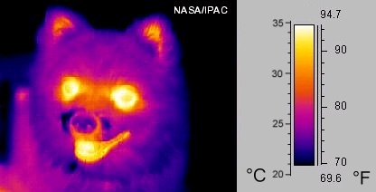
- Sensor type (e.g. colour, monochrome/greyscale, thermal, IR)
- Optics (e.g. fisheye lens, wide FOV, 360deg, focal lengths)
- Frame rate (e.g. high-speed cameras)

Most of the concepts covered in this tutorial will in some way apply to all of these.
One particular variety of camera is the depth camera which will be covered in greater depth (pun intended) in the next tutorial, but make sure to read this one first as it will be used as a foundation.
Capturing & Storing images
When a camera takes an image, the light that is bouncing around the world passes through a lens and an aperture, and then onto a sensor. This data is recorded and stored as pixels. This is a 2D array of measurements of the intensity of light at that point on the sensor.
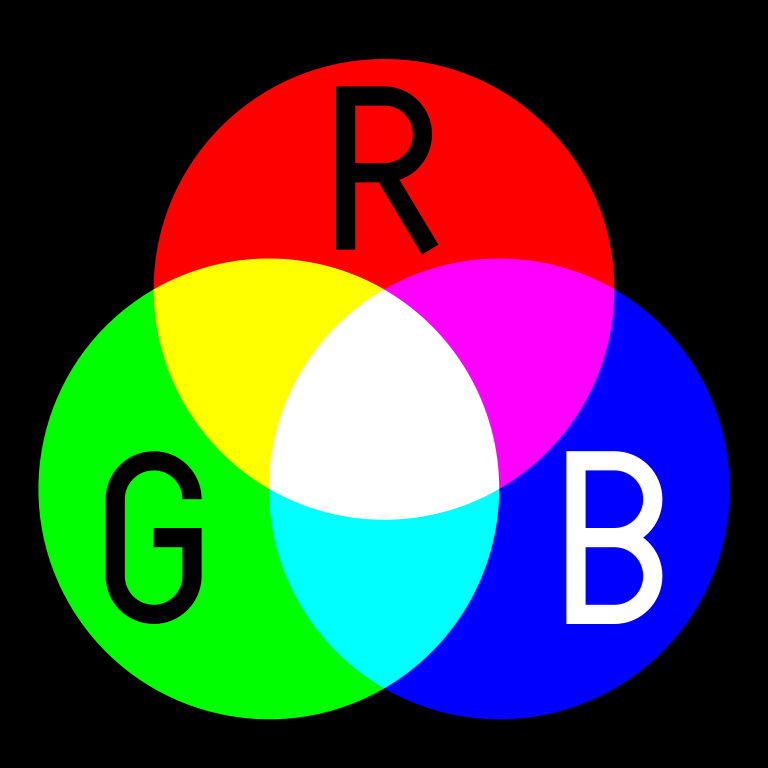
For a grayscale image, this is pretty straightforward - one measurement per pixel. But for colour images it’s a bit more complex. There are a few different methods that can be used, but the most common one on computers is to split the colour information up into three different channels - red, green and blue. By combining different amounts of each of these base colours, we can make pretty much any colour. None of any colour is black, maximum of all three combined is white, and anything in between.
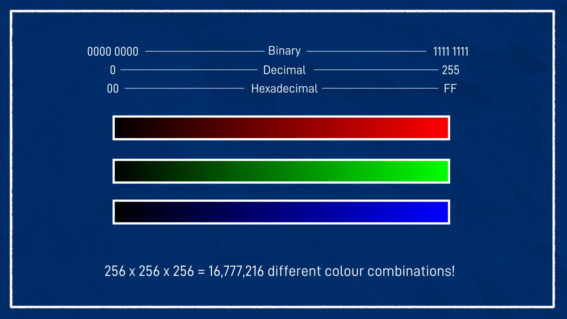
Most commonly, we use 8 bits per colour channel, per pixel, which gives us a range of 256 different values, 0 as a minimum and 255 as a max. And we usually order the three colours as red, green, blue, or RGB.
Sometimes though, you’ll come across other modes. For example, your camera might give you 16 bits per pixel, or you use a library like OpenCV which stores data as BGR. In any case, the overall principle is the same.
Image Compression
This format (3x8-bit values per pixel) is very easy for computers to work with, but isn’t particularly space-efficient, so we often want to utilise compression. This is especially important when we want to send image messages over a network, a common process in robotics.
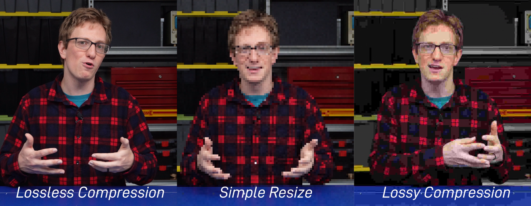
To save space, we could just resize the image and throw away a bunch of pixels, but formats like JPEG and PNG can be a bit smarter than this, they let us shrink the data size without shrinking the actual image - we don’t lose any pixels. The computer uses some clever algorithms to throw away less important information - for example if there is a big dark patch, rather than storing “0 red, 0 blue, 0 green” for every individual pixel it may be able to group them. PNG does this in a way that no information is lost at all, whereas JPEG is lossy, sometimes pixels that are near each other can blend together a bit.
Focal Length
There are many parameters that contribute to the final image of a camera, but one worth having a basic understanding of is focal length. This is how far away the sensor inside the camera is away from the lens, but it’s kind of meaningless without knowing the size of the sensor. Instead it’s often easier to talk about the horizontal field-of-view, the angle spanned from the left side of the picture to the right side.
Then, when we increase the focal length, we decrease the field-of-view, making that angle tighter, which is zooming in. You can see in the image below that with a large focal length it can only see just above the person, rather than all the trees.
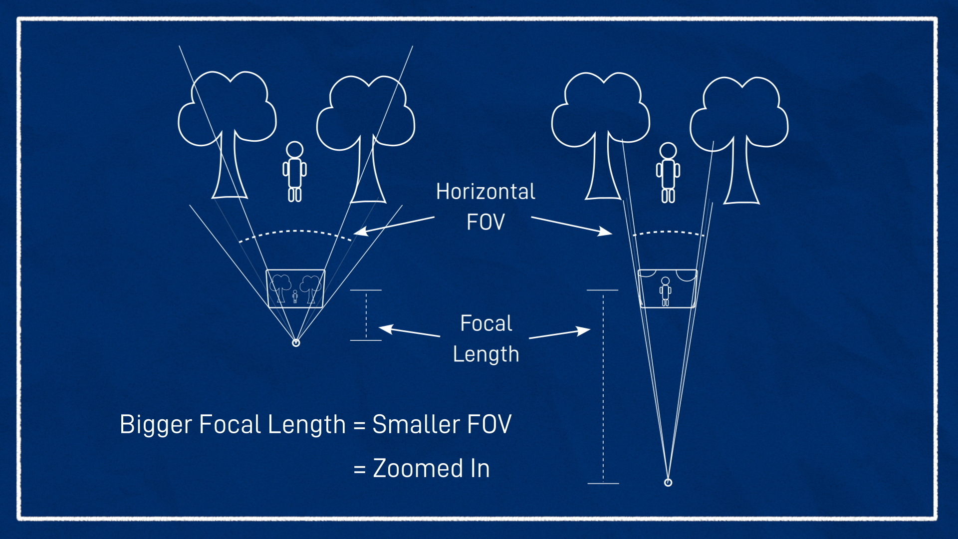
Often in robotics, we care about seeing as much as we can around us, and so we use cameras that are zoomed out with a fairly wide-angle field-of-view, or a short focal length.
Also, if you do ever need to perform the conversions, here’s the equation, it’s just some plain trigonometry.
The picture above is very much not to scale and is also not quite a proper depiction of the lens-sensor interaction, but hopefully it helps to understand the effect of focal length adjustment. For more detail, check out Wikipedia and the referenced links.
Coordinate systems
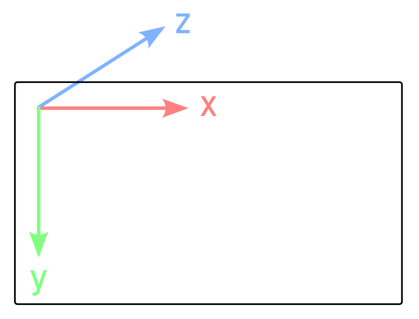
The last thing to note briefly is coordinate systems. Typically when working with images, the X direction is from left-to-right, and the Y direction is top-to-bottom. According to our right-hand rule, this would lead to a Z direction into the page (or pointing forward from the camera). This will come up again soon when we look at how ROS deals with things.
Cameras and Images in ROS
Now that we’ve got a general understanding of how images and cameras work, let’s see how they’re used in ROS.
Image Messages
ROS stores images using the sensor_msgs/Image message type.
This file is actually pretty simple and essentially boils down to a big array (the final data field):
std_msgs/Header header
uint32 height                # image height, that is, number of rows
uint32 width                 # image width, that is, number of columns
string encoding       # Encoding of pixels -- channel meaning, ordering, size
uint8 is_bigendian    # is this data bigendian?
uint32 step           # Full row length in bytes
uint8[] data          # actual matrix data, size is (step * rows)
Below you can see image_encodings.hpp which lists the many options for how the pixel data can be encoded.
1
The frame Header contains the image acquisition timestamp - nothing too surprising - but the associated TF frame must be the camera optical frame.
Coordinate Frames
One of the most confusing aspects of working with cameras in ROS is the way coordinate frames are used.
In order for the camera data to be processed correctly it needs to be associated with a coordinate frame - no big deal. But what orientation should the frame be in? We’ve seen in earlier tutorials that in ROS, the standard orientation is to have X forward, Y left, and Z up. However as we saw just above, the standard outside of ROS when working with cameras and images is to have X right, Y down, and Z forward.
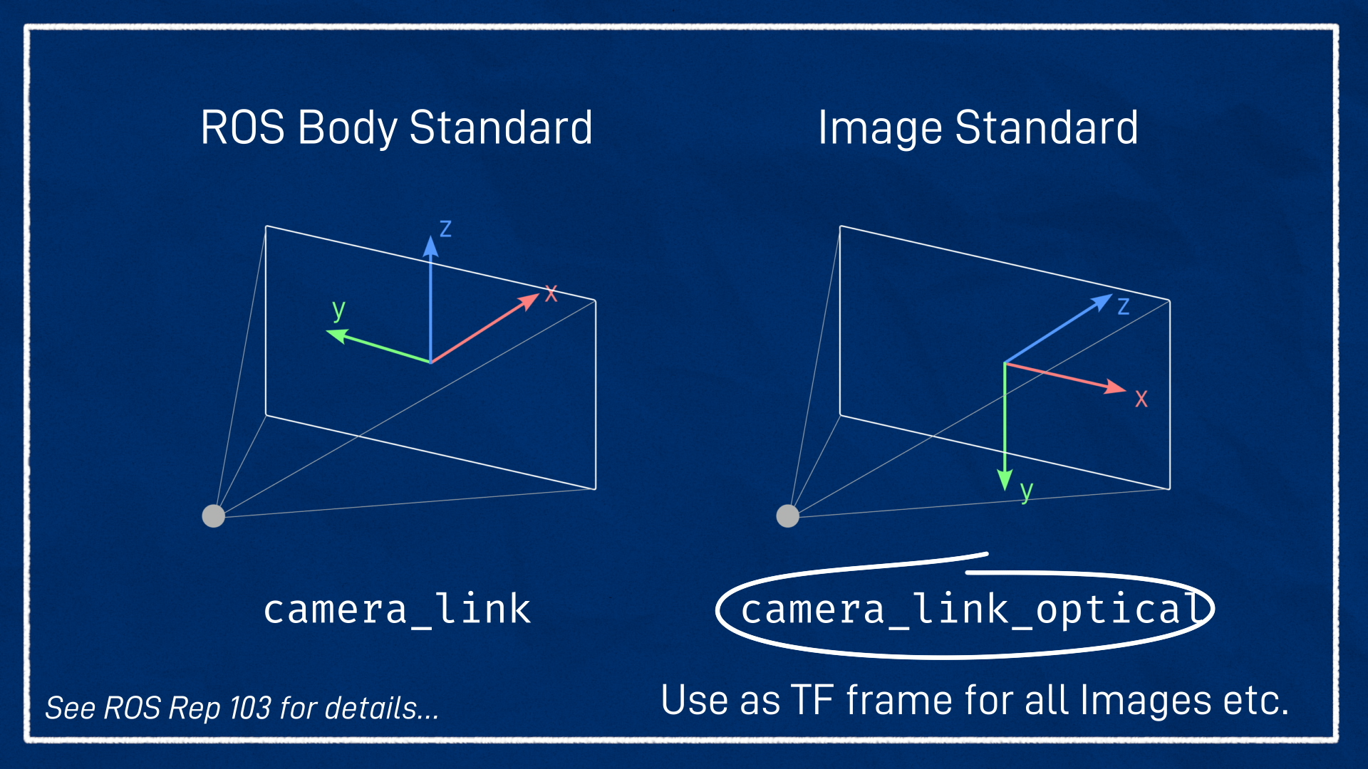
To accommodate this, the standard approach is to create two different frames that are located in the same location - the optical centre of the camera - but with different orientations. One should follow the ROS body convention and be named something like camera_link, and the other should follow the standard image convention and contain the _optical suffix (i.e. camera_link_optical). The Image and CameraInfo message headers should reference the camera_link_optical frame, but the other link is still there if needed.
We’ll see this in action very soon when we update our URDF.
Camera Info
ROS provides another type called sensor_msgs/CameraInfo. This provides a bunch of metadata about the camera - the lens distortion and so on - so that the data from the image can be correctly interpreted by the algorithms. The topic is typically called /camera_info and is in the same namespace as the Image topic, e.g. /my_camera/image_raw would match to /my_camera/camera_info.
In this tutorial we won’t spend any more time looking at the camera info.
ROS provides the image_proc/image_pipeline packages to assist in converting the /image_raw topic into more useful data, which is often published to topics with names like /image_color or /image_rect. Again, that's out of the scope of this tutorial, but you might find the CameraInfo documentation and ROS 1 image_proc documentation helpful.
Camera driver node & Image messages
First up, just like the LIDAR in the previous post, we’ll always have a camera driver node. This is a node that is designed to communicate with whatever particular camera hardware you have, and publish the stream of data. It’s common for the driver node to be able to control various aspects of the camera stream, e.g. resolution and frame rate.
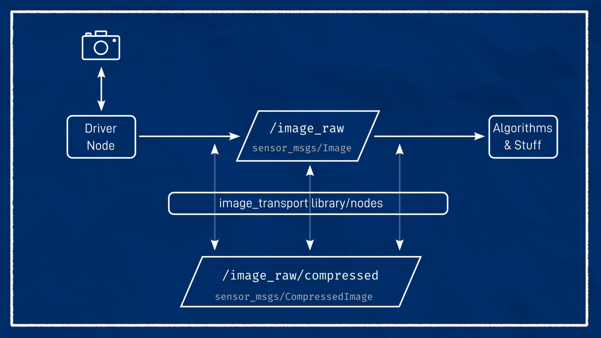
That driver node then takes the data stream coming from the camera, and publishes it to a topic of type sensor_msgs/Image. Again, like we saw with LIDAR, that means that algorithms just need to be written to work with an Image message, and as long as your camera has a driver, it will work, which is great. Note that there is also another type called sensor_msgs/CompressedImage that is designed to work with compressed images.
The unprocessed Image topic published directly by a camera driver is often called /image_raw (to indicate an unprocessed image, not to be confused with the RAW format used in professional photography). If there is a compressed version then it will just add /compressed to the end of the base topic - so in this case it would be /image_raw/compressed.
To assist in dealing with compression, ROS provides the image_transport tools. If nodes are written correctly, image_transport can handle all the compression/decompressions automatically without much trouble. If they aren't (e.g. the drive is only publishing a compressed image), image_transport provides its own node to "fill in the gaps", which we’ll explore later.
Note that Image messages have a Header, which contains the time of the image measurement and also the coordinate frame of the camera that took it.
Simulating a Camera in Gazebo
Just as in the previous tutorial with the LIDAR, we’ll first get a camera simulated and working in Gazebo before we try to connect to a real one. If some of the concepts are being skimmed over too fast, try checking that tutorial for clarification.
Adding a Camera link/joint to our URDF
We'll start off very similar to the lidar (so similar that you could probably copy lidar.xacro and replace a couple of names):
- Create a new file, called
camera.xacroin thedescriptiondirectory - Add the
<robot>tags - Create a link called
camera_linkand a joint calledcamera_joint, attached (fixed) to thechassis - Add
<xacro:include filename="camera.xacro" />to ourrobot.urdf.xacro
For this example, the camera origin will be at the front-centre of the chassis (305mm forward in X and 80mm up in Z). Note that at this point we are still following the ROS convention of "X-forward". I have not added any rotations as my camera is facing directly forward, but if yours is tilted you can add the appropriate rotation.
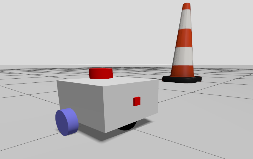
1
I've represented the camera as a small, red, rectangular prism. Since my camera is small and fixed to the chassis, I am skipping the collision and inertial parameters. If your camera protrudes from the chassis it should probably have collision, and if it is not on a fixed joint it will need inertia.
Add the optical link/joint
Now we need to add the “dummy” link called camera_link_optical mentioned earlier, to account for the different coordinate standards - transforming from the standard ROS robot orientation (x-forward, y-left, z-up) to the standard optical orientation (x-right, y-down, z-forward).
For a camera link called camera_link, the following block achieves this.
1
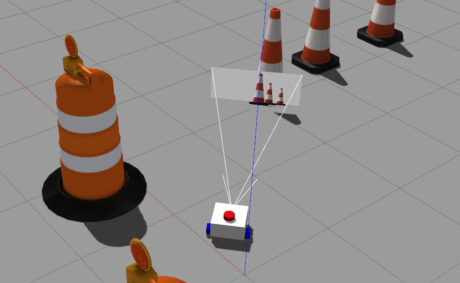
If we were to rebuild and rerun now, we’d see the following:
Camera Sensor Simulation
Finally, now that our links and joints are set up we can add a <gazebo> tag with a <sensor> tag inside, to tell Gazebo to simulate a camera. Note again that this is the Gazebo tag for camera_link, not the optical one.
1
Previous versions of Gazebo required a <plugin> tag to be added, but now this is handled by the Sensors plugin we added to our world SDF file.
If the overall structure is confusing, it's worth going back to check out the lidar tutorial. Now let's explore what is new - the parameters in the <camera> tag.
I've set the following:
- Horizontal field-of-view is 1.089 radians, to roughly match the Pi camera
- The image is 640x480 pixels, stored as 8-bit RGB
- The clipping planes (distance the camera can see) is set to a minimum of 0.05m and a maximum of 8m
<camera>
    <horizontal_fov>1.089</horizontal_fov>
    <image>
        <format>R8G8B8</format>
        <width>640</width>
        <height>480</height>
    </image>
    <clip>
        <near>0.05</near>
        <far>8.0</far>
    </clip>
</camera>
Now, we can relaunch Gazebo and we’ll be simulating a camera! While the new Gazebo does not support the nice frustum preview from Gazebo Classic, we can still add an Image Display from the 3 dots menu in the top right to get a preview of what our camera is seeing.
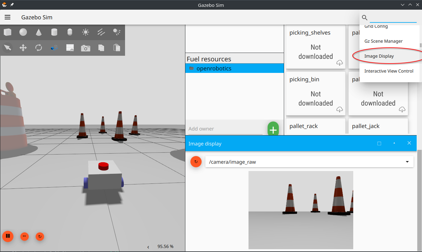
That tells us it’s working inside Gazebo, but how do we know if it’s made it out to the rest of ROS?
Getting the data to ROS
Unlike the rest of the topics, Gazebo has a special way to get image data out to ROS. We will use the image_bridge node from the ros_gz_image package (instead of the parameter_bridge node from the ros_gz_bridge package).
We need to add the following block to our launch_sim.launch.py just below the normal bridge, and also make sure we add it to our final LaunchDescription call.
1
For nodes that use camera data to work correctly, we also need to bridge the camera_info topic. This will go via the regular bridge, so we need to add the following to the end of our gz_bridge.yaml.
1
Visualising Camera Data
When we want to check if our image data is being published correctly, it’s not usually practical to use ros2 topic echo - we want to actually see the data.
To check that the camera is actually being simulated correctly, relaunch the simulation then start RViz and add an Image section. Set the topic to /camera/image_raw and make sure the Fixed Frame is set to something on your robot (e.g. base_link, or if that doesn't work, camera_link).
Sometimes I have had issues with the QoS not allowing me to see the data. If you are having trouble, try changing the Reliability policy to Best Effort.
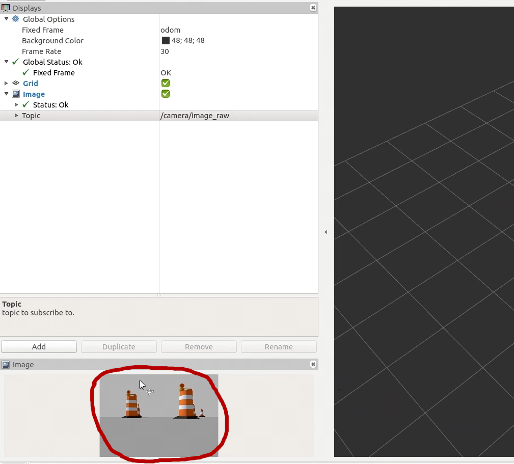
Hopefully you should see a little window into our simulated world!
RViz also offers the Camera display which is similar, but overlays the image onto the 3D view of the world. If we had other things displayed in RViz (e.g. models of other robots) and everything has been calibrated and undistorted correctly, this would let us check it all lines up.
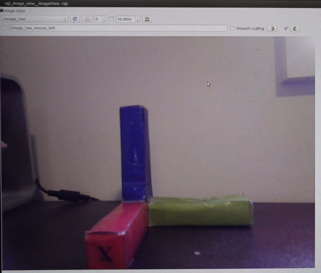
A couple of other nodes you can experiment with for viewing data are image_view and rqt_image_view, which are sometimes a bit less finicky than RViz, especially around transform frames and image compression.
Setting up the real camera
Now that we've got a virtual camera going, we can integrate a real camera. ROS has drivers for a variety of different cameras but here we will look at USB webcams and Raspberry Pi Cameras (and similar).
Before we start, we want to install a few packages:
sudo apt install v4l-utils ros-jazzy-image-transport-plugins ros-jazzy-rqt-image-view
Also, use the groups command to confirm you are already in the video group (to allow camera access).
If not, run sudo usermod -aG video $USER (this requires log out/restart to take effect).
USB Webcam
The camera_ros node from the next section can also be used with USB webcams, and without the requirement to compile from source as those steps suggest.
We can install the driver node with:
sudo apt install ros-jazzy-usb-cam
Then run it with:
ros2 run usb_cam usb_cam_node_exe
If you are trying to run a USB webcam at the same time as a Pi camera you may find the Pi camera takes over the default video device and you need to override it with the video_device parameter. To find the correct device you can run the following command (for me it was /dev/video8). You may need to install v4l-utils if you haven't already.
v4l2-ctl --list-devices
You can test this with ros2 run rqt_image_view rqt_image_view, but remember the raw feed requires a lot of bandwidth if you are viewing over the network.
I found a few issues when running this driver with a Logitech C922:
- The normal
compressedtopic was green with weird artifacts - The
theoratopic worked once, then if I switched topics and back again inrqt_image_viewit didn't work - The
zstdtopic worked ok but had more latency.
The best documentation is the old ROS wiki, although some parameters have changed slightly, so you can also look through the GitHub repo for more documentation, example parameters/launch, etc.
To make it easier to run, we set up a launch file. Here I have created a launch argument for the video device, and some other parameters are hard-coded. This also places the node in the camera namespace to match the simulated data.
1
Raspberry Pi Camera
One neat thing about the Raspberry Pi is that it has a dedicated camera connection port, with a variety of compatible cameras. You may want to use one of these when building your robot.
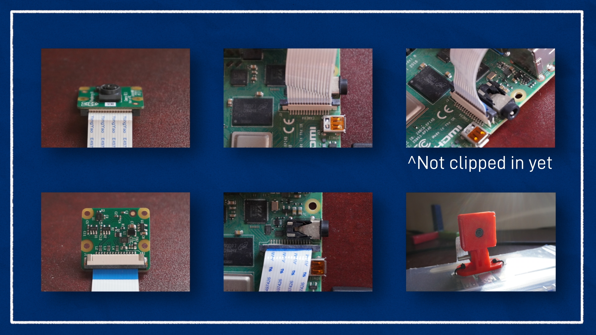
Shut down the Pi and plug in the camera. One end of the ribbon cable should go into the port on the board and the other end should go into the camera. Check out the images below to make sure you get the orientation correct (the blue bit on the ribbon should be on the same side as the black clip on the connector).
An earlier version of this tutorial made use of the now-deprecated "legacy camera stack" for Raspberry Pi, and the v4l2_camera package. These libraries do not support newer hardware so I have updated it with the camera_ros package which uses the new libcamera backend. Unfortunately this package must be built from source for full compatibility. For more information about the various stacks, see this page.
Tested with the official Raspberry Pi Camera Module 3 on a Raspberry Pi 5 running Ubuntu 24.04
Install libcamera Dependencies
As per this page we need to install a bunch of dependencies. For some reason libqt5widgets does not work but it also doesn't seem to stop us so we can leave it out. Simplifying those commands gives us:
sudo apt install -y libboost-dev libgnutls28-dev openssl libtiff-dev pybind11-dev qtbase5-dev libqt5core5a meson cmake python3-yaml python3-ply libglib2.0-dev libgstreamer-plugins-base1.0-dev
Compile libcamera and camera_ros
The camera_ros package contains very good instructions for how to build both libcamera and camera_ros from source with Pi camera compatibility. These are reproduced below with the relevant changes for our system. Note this is adding to our robot_ws workspace - you may prefer to compile it in a separate workspace and source both when running.
# Make sure you have sourced your ROS installation first!!

# Enter workspace source directory - if your workspace is elsewhere you can change accordingly
cd ~/robot_ws/src

# Install colcon meson support
sudo apt -y install python3-colcon-meson

# Clone libcamera (raspberrypi fork)
git clone https://github.com/raspberrypi/libcamera.git

# Clone camera_ros
git clone https://github.com/christianrauch/camera_ros.git

# Resolve dependencies
cd ..
rosdep install -y --from-paths src --ignore-src --rosdistro $ROS_DISTRO --skip-keys=libcamera

# Build! (If you have a modified build command you usually use, run that instead)
colcon build --symlink-install
Run the camera_ros node
First, source your workspace (e.g. source ~/robot_ws/install/setup.bash), then:
ros2 run camera_ros camera_node
You can check out the readme on the GitHub repo for other ways to run, and topics/parameters you can set.
If you have more than one camera connected, be sure it is connecting to the correct one!
Again, to make it easier to run we can use a launch file, with the parameters in a config file.
1
Calibration
Usually, an important part of running a camera on a robot is calibrating it, but we will leave that out of the scope for this tutorial as it is not needed for our basic applications.
Decompressing and republishing image data
As one last note, if we ever need to manually deal with compression/decompression of images, we can first check which plugins image_transport has installed:
ros2 run image_transport list_transports
Then, to republish a topic we need to specify the type of the input, then the type of the output. We also need to remap some topics, which are in the format {in/out}/{type} (with no type for uncompressed/raw). For example, to remap from a compressed input topic to a raw output topic we use:
ros2 run image_transport republish compressed raw --ros-args -r in/compressed:=/camera/image_raw/compressed -r out:=/camera/my_uncompressed_image
Note, with
image_transport,rawmeans "uncompressed" and has nothing to do with the "raw" inimage_raw.
Conclusion
Now we've got a handle on how cameras and images work in ROS, we can simulate a camera in Gazebo, and connect to a real camera. In the next post, we'll keep looking at cameras, but specifically depth cameras which also return a distance to each pixel.