Adding Lidar
In this post we'll cover a bunch of different aspects of using LIDAR sensors with ROS, including simulation in Gazebo as well as connecting to a real lidar.
What is LIDAR?
So what is LIDAR? Lidar stands for Light Detection And Ranging, similar to sonar and radar with sound and radio waves respectively. Lidar technology uses beams of light to sense the range to an object. This can be very useful to a robot as it can sense the distance to a target or obstacle, and create a local "map" of the world around it.
There are a huge variety of lidar models on the market, employing a range of different technologies, at different price points. For now, we can boil this down into three categories:
- 1D - Measures the distance to a single point. These are often used as "digital tape measures". Alone, these have limited usefulness, e.g. for a UAV to detect height from the ground or a mobile robot to detect the distance to a wall directly in front.
- 2D - The most common type of lidar, this measures many points in a scan plane. The simplest models are simply a 1D lidar attached to a motor with an encoder. These are often used on mobile robots to create a floor plan to navigate around. Models vary in frequency, range (maximum distance), resolution, and horizontal field-of-view. These are sometimes called "laser scanners".
- 3D - There are an increasing number of 3D lidars on the market, that utilise a variety of methods and technologies. Rather than a single 2D scan plane, these lidars see in three dimensions. Some models can be effectively treated as 3D cameras, returning an image with a distance measured to each pixel.
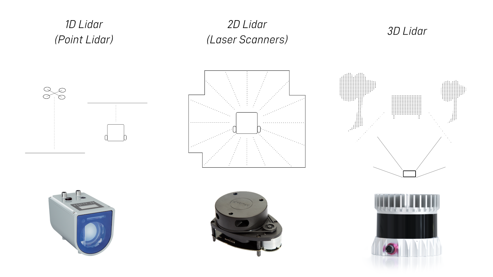
This tutorial (and the robot I’m building) will focus on 2D lidar as they are very effective and some models are available at quite a low price point.
Lidars in ROS
Because Lidars are such a common sensor, ROS has really good support for them. When you’re using other software, it can be a real pain to work with different lidar models and manufacturers, since they all speak different languages and protocols. This is where ROS really shines, as long as there’s a ROS driver for your lidar, it will handle all the complicated stuff and just publish a message in a common format (which we'll see below). Then, as long as your software is written to use that format, it will work with pretty much any lidar you can find!
2D Lidar and LaserScan
ROS has a specific message type for 2D laser scan data, called sensor_msgs/LaserScan. Each LaserScan message contains the data for a single sweep of the sensor, and is basically an array of floats representing each range measurement (in metres), along with some extra parameters to aid in understanding the data properly. The LaserScan message also tells us which TF frame the lidar is attached to, so that the rest of the system can figure out where the hit points are in 3D space. This is especially helpful for things like combining scans from multiple sensors at once.
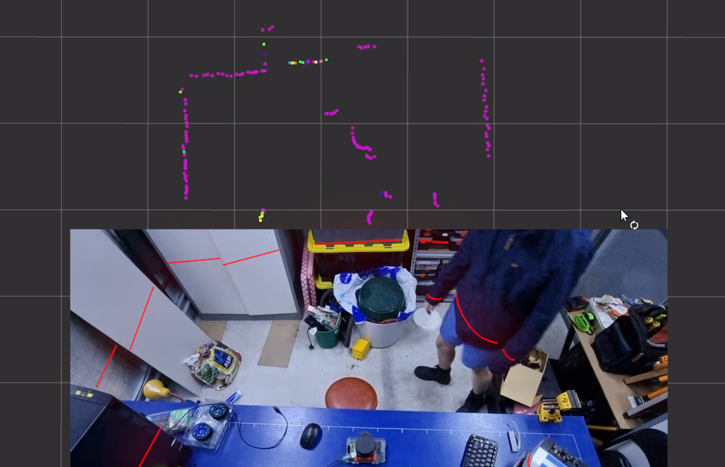
(Note, the red lines in the image are drawn on for clarity)
3D Lidar and PointCloud2
When we're using 3D lidar, or sometimes if we have a 2D lidar on a motor to sweep the scan plane through space (essentially a DIY 3D lidar), it is usually more convenient to treat the data as a point cloud. A point cloud is just a whole lot of points in 3D space, and can provide a much richer representation of the surroundings than a 2D scan. ROS handles point clouds using the sensor_msgs/PointCloud2 message type. When using 3D lidars, the ROS driver will typically be set up to publish a PointCloud2 directly.
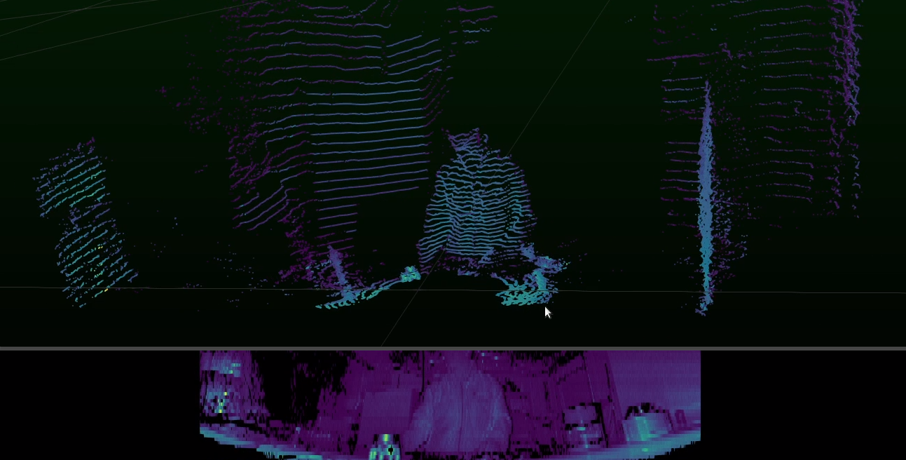
The rest of this tutorial will focus on 2D lidar, but some of the concepts will also apply to 3D lidar. In an upcoming post we'll take a look at depth cameras, which are very similar to 3D lidar and also use PointCloud2.
Simulating a Lidar in Gazebo
To start getting our feet wet, let’s simulate our lidar in Gazebo. Even if you don’t plan to use Gazebo, you should still read this bit as parts of it are relevant regardless. For my example I’ll be adding it on to a robot from an earlier tutorial, this is actually part of a larger series on building an autonomous robot, so you can go check that out if you need to.
Adding a Lidar link/joint to our URDF
We'll start by adding a lidar joint to our URDF. This provides a new TF frame to act as a reference point for our laser scan data. We'll also add a cylinder to act as the visual (and collision/inertial) element for the simulation and visualisation.
Like we did with the gazebo control code, we'll add these in a separate xacro file to keep things neat and modular. So we want to create a new file in the description folder called lidar.xacro (for the new content), and also add an include in our robot.urdf.xacro to include it.
Inside lidar.xacro we'll add our joint and link tags. We'll fill in the link tag details soon, but here you can see:
- I've named the link
laser_frame, but you can call it whatever you want - It's attached to my
chassiswith a fixed joint - It's 100mm forward in X and 175mm up in Z, from the
chassisorigin (which was the bottom-rear of my chassis)
1
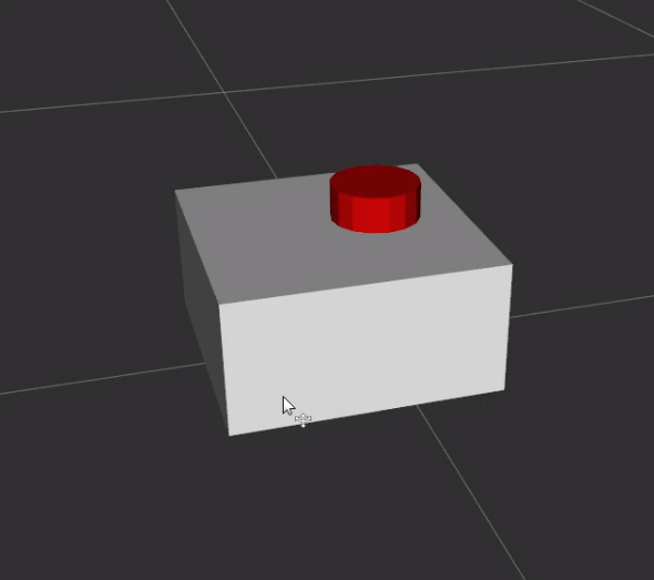
To create the geometry of our lidar link - a short cylinder - we can be sneaky and copy from our drive wheels. We can change the colour to red and make sure we add that as a material in our robot_core.xacro.
1
If we were to spin this up now we'd see the following in RViz.
Simulating Sensors in Gazebo
When we want to simulate a sensor in Gazebo, we need to choose a link to attach the sensor to, and make sure we have a <gazebo> tag for that link with a <sensor> tag inside it:
1
That tells it to:
- Add a
gpu_lidarsensor to this link - Have the sensor origin at the link origin
- Visualise the simulated measurements in the viewport (does not work anymore - see later note)
- Update virtual sensor at 10Hz
- Save the data to the (Gazebo internal)
scantopic - we'll get this into ROS later. - Set the sensor data frame to be the same as the link name
In future versions, gz_frame_id will be replaced with simply frame_id
The <lidar> tag will contain the parameters for our simulated lidar. Ideally you want to set these parameters to be as similar as possible to your actual lidar. As an example, I set the following parameters for 360° scanning with one ray per degree and a max range of 12m:
<lidar>
    <scan>
        <horizontal>
            <samples>360</samples>
            <min_angle>-3.14</min_angle>
            <max_angle>3.14</max_angle>
        </horizontal>
    </scan>
    <range>
        <min>0.3</min>
        <max>12</max>
    </range>
</lidar>
Previous versions of Gazebo required a <plugin> tag to be added, but now this is handled by the Sensors plugin we added to our world SDF file.
Bridge to ROS
We also need to update our gz_bridge.yaml file so that the internal Gazebo topic is mapped over to a ROS topic. The expected scan topic is there with a LaserScan message, and for compatibility with 3D lidar algorithms, scan/points contains the same scan as a PointCloud2.
1
Testing & Visualisation
Now we want to rerun our simulation (ros2 launch my_bot launch_sim.launch.py).
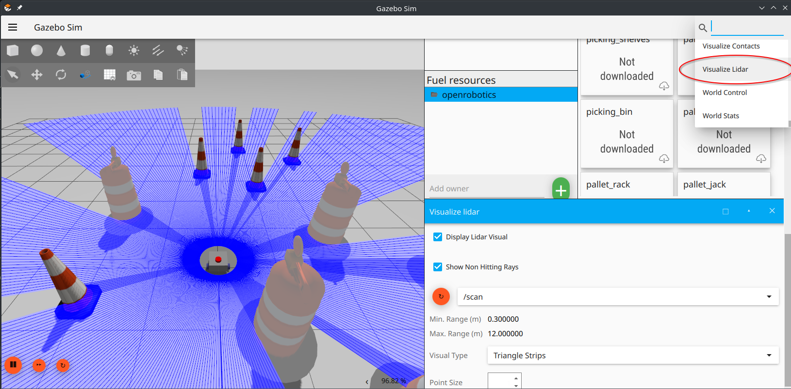
To visualise the lidar beams, click the three dots in the top-right corner and add a Visualize Lidar plugin, you might need to scroll down to see it in your panel. Then click the reload button and select the /scan topic. Make sure you have some obstacles to scan!
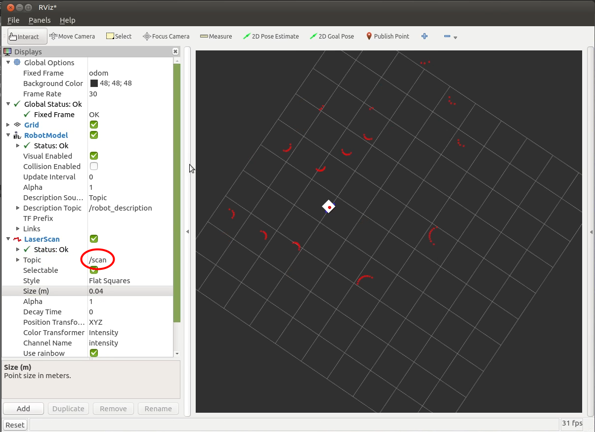
To view the output in RViz we can first set it up like normal (add a RobotDescription, set the Fixed Frame to odom). Make sure to hit the "Reset" button if you already have RViz open.
Then, we can click Add->LaserScan, and in the dropdown set the topic to /scan.
Hopefully you should see the laser dots appear in the RViz window and move around as the robot drives. They should stay in roughly the right spot, but there might be a little bit of drift due to the simulated wheel slipping.
Even though this is just a simulation, we can use the same RViz tool to visualise data from a real laser, so let's take a look at that now!
Setting up the real Lidar
Now that we have things working in Gazebo, let's set up a real lidar. For the example, I'll be using the RPLIDAR A1 by SLAMTEC. This is one of the cheapest 2D lidars on the market, and thanks to ROS it's very easy to get up and running!
Remember to push your changes to git before pulling to the robot!
Wiring up
The first step is to plug it in. This is easier said than done, since (in my experience) it can be pretty fussy about which micro-USB cables it works with, so if you are having trouble then try a different cable. Simply plug it into the provided adapter, the adapter into the lidar, and the other end of the plug into your computer!
Installing the driver
Now we need the driver software, to talk to the laser and publish a LaserScan topic. This can be installed by running the following command:
sudo apt install ros-jazzy-rplidar-ros
There have been a few different versions of the rplidar_ros package released by different maintainers at different points in time. They have slightly different node names, parameters, features, fixes, etc. At time of writing, the instructions below should work with the version in the repos for recent distributions.
If you are having trouble you can try cloning various branches of the two main versions (official and allenh) into your workspace and compiling from source.
Talking to the Lidar
Next we need to run the driver. The package name is rplidar_ros and right now, for the version installed on the apt repo, the node name is rplidar_composition, which is a weird name, for a good reason, but that doesn’t really matter right now.
Before we rush in and run that, there are a few optional parameters to set too. As an example, here are the ones I'm using:
-p serial_port:=/dev/ttyUSB0- The serial port the lidar is on (more on this later!)-p frame_id:=laser_frame- The transform frame for our lidar-p angle_compensate:=true- We just want this setting to be on. If you don’t set it, it says it’s on but it doesn’t actually work properly-p scan_mode:=Standard- Which scan mode the lidar is in, which controls how many points there are and stuff. I’ll set mine to standard but you can check the manual and find an option that works for you.
So the final run command will be:
ros2 run rplidar_ros rplidar_composition --ros-args -p serial_port:=/dev/ttyUSB0 -p frame_id:=laser_frame -p angle_compensate:=true -p scan_mode:=Standard
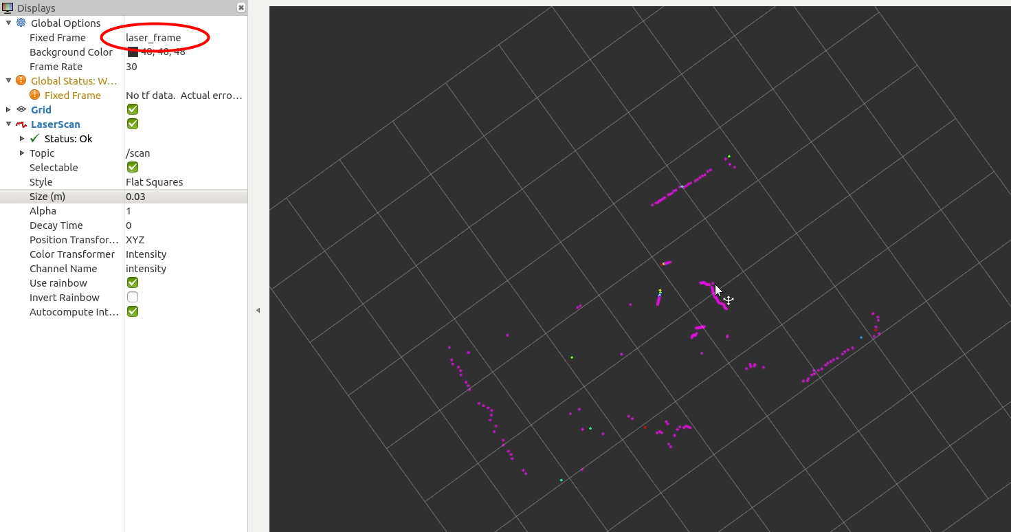
The driver node should now be publishing LaserScan messages. To check this, we can again use RViz. If robot_state_publisher isn't running, then we'll need to manually specify the fixed frame by typing in laser_frame. By default, the colours of the points should reflect variations in the intensity of the measurement.
If you are having trouble connecting to the lidar here are two things to check:
- Make sure your user is added to the
dialoutgroup (sudo adduser $USER dialoutthen reboot). Alternatively you can try the udev rules - For certain Ubuntu versions, you need to
sudo apt remove brlttyto uninstall the braille terminal support which can "steal" the serial port. Ubuntu 24.04 should not have this issue.
Extra tips
Lastly, here are a few extra tips when working with the RPLidar driver:
Better serial paths
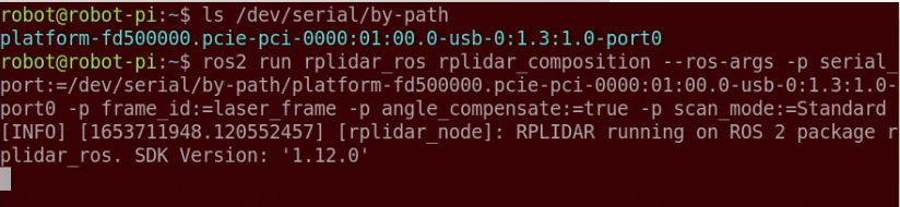
Sometimes we’ll have multiple serial devices. Maybe you’ve got an Arduino as a motor controller like I will, or you’ve got multiple lidars. In this case, Linux won’t always assign the same serial ports each time. To get around this, rather than using something like /dev/ttyUSB0, we can instead use /dev/serial/by-id or /dev/serial/by-path. As long as you plug things in to the same USB ports every time, the by-path one will always work (I think). So
Starting/stopping the motor
Since we don’t necessarily want the lidar spinning all the time, there’s a service to start and stop it. It takes an empty parameter so we can run the following command to stop the motor, and the similar /start_motor to start it back up again.
ros2 service call /stop_motor std_msgs/Empty {}
Putting it in a launch file
As with everything else, we don’t want to have to remember how to run the node every time, so instead we can make a launch file to do it for us. Check out the code below for an example.
1
This is a good time to push your changes!
Killing the node
Sometimes the driver node can lock up which is annoying. You can kill it by opening another terminal and typing:
killall rplidar_composition
Up Next
Having a lidar attached to our robot, means we’ll be able to use SLAM (simultaneous localisation and mapping) algorithms to develop an autonomous navigation system (similar to many robotic vacuum cleaners).
Before we get to that though, we’re going to add some more sensors, so in the next few posts we’ll be looking at cameras - both regular cameras and depth cameras - and getting them to work with ROS!