ros2_control Concepts & Simulation
Why do we need ros2_control?
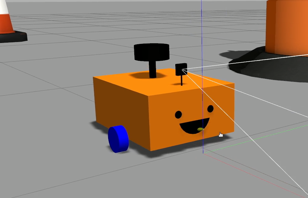
Today we’re going to learn how to solve a problem that literally every robot has, and that's control. A core part of every robot is to take in some kind of input (from an operator or the environment), do some thinking, and drive an actuator - whether that's a motor, a hydraulic system, or something else.
There are many different kinds of actuators and interfaces out there, and many different control methodologies that we use to use to solve problems with them. But within this huge universe of options, there’s actually a lot of commonality, and if we don’t have some kind of standardised system - if we’re just writing a custom controller and custom interface for every application - we end up wasting time rewriting things and solving problems that people have solved hundreds of times before
Instead what we want is a framework where we can write the drivers for different hardware platforms, and the algorithms for different control methodologies, and have these speak a common language so we can pick and choose what we need.
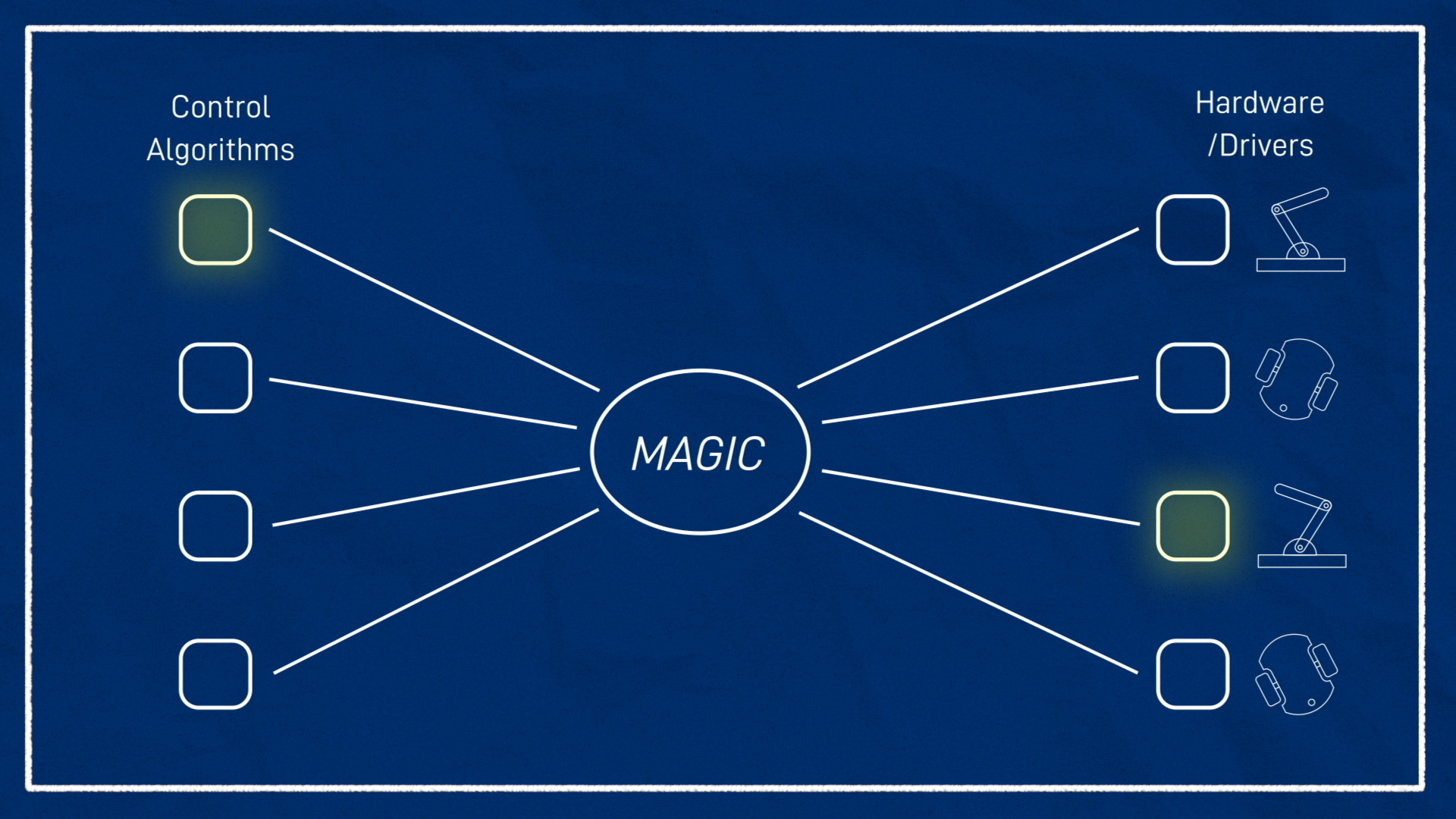
You might think that this is a problem well suited to ROS topics - just create some standard messages, write nodes for the controllers and drivers, and you’re done! One problem with this approach is that although topics are generally pretty fast, we want something like this to run really fast, there should be no delay between the controller and the driver. That's where ros2_control comes in.
The ros2_control framework is a powerful and complex beast, so to understand it we’re going to have to take it step by step. It might be tempting to give up and say “it would be quicker to just write this from scratch” and although maybe it would be (probably not), the power of ros2_control is not just that it can make individual projects simpler, but that it makes reusing code, upgrading, and modifying systems way easier.
In this tutorial we’ll look at how ros2_control works, and how to use it in a Gazebo simulation, and then in the next tutorial we’ll get it up and running on a real robot so we can drive it around.
Controller manager
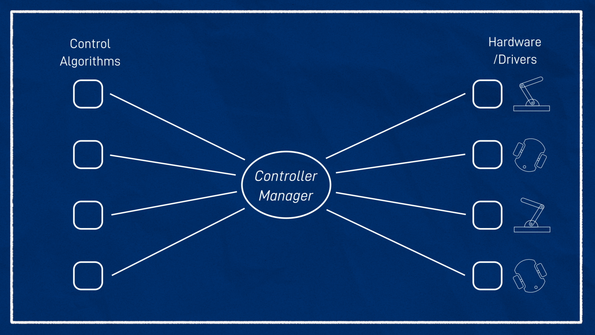
At the centre of it all we have something called the controller manager. It’s going to find all the bits of code for our hardware drivers and our controllers and link them together. To achieve this, it uses a plugin system - so each of these things isn’t running its own executable, it’s just a library that is loaded up at runtime and has a set of functions that will link in to the system.
Hardware Interfaces
Let’s take a look at the hardware side first.
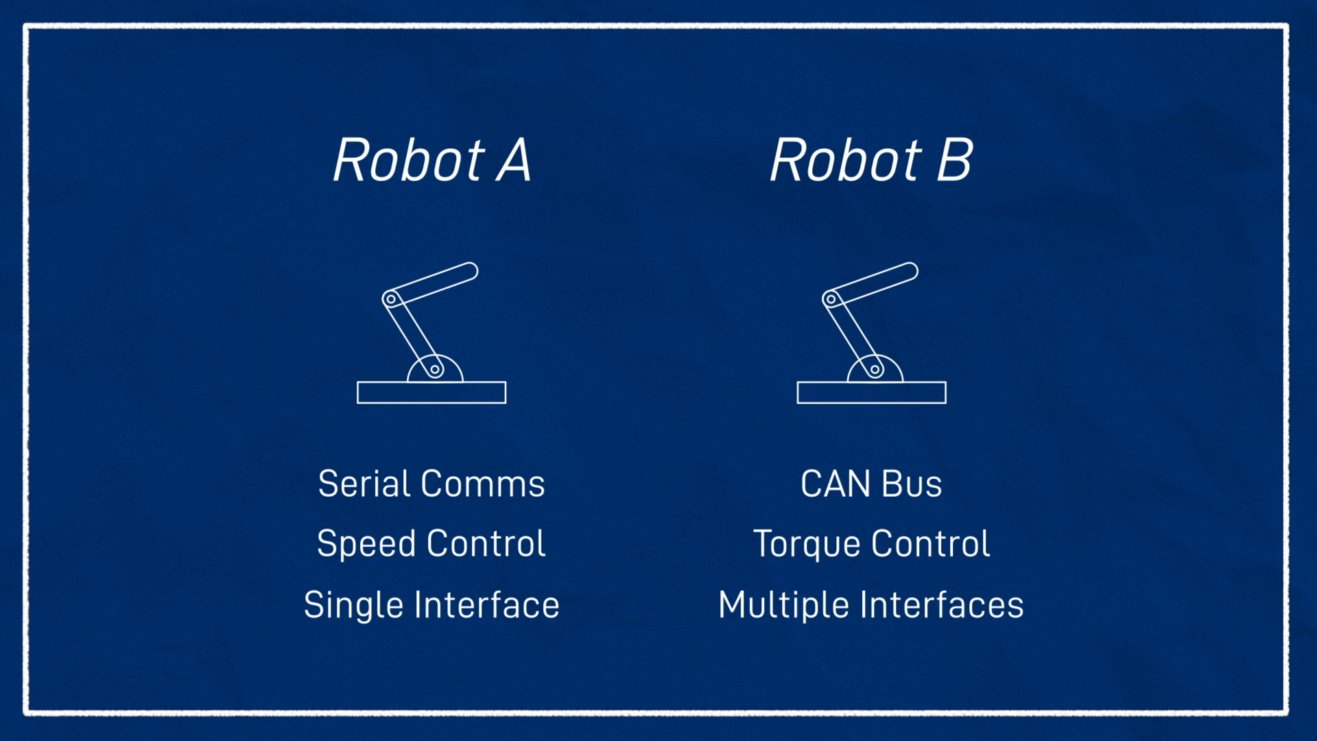
Different hardware needs to be controlled differently. You might have two very similar-looking robots, but one’s motors speak via serial, and the other via CAN bus. One might let you control speed and position, the other only speed, or speed and torque. One might have a single comms interface for all motors, the other might have an interface per motor.
Whatever our hardware looks like, to use ros2_control with it, we need something called a hardware interface (sometimes called a hardware component). This is a bit of code that talks to the hardware and exposes it in the ros2_control standard way. Ideally if you’ve bought a robot, the creator or someone else online will have written the hardware interface for you.
If you’re following along with my build series you’ll be able to use the one I’ve written, but otherwise you might need to write one yourself.
The hardware interface acts as an abstraction so that as users, all we need to understand is the way it represents our hardware, which is through command interfaces and state interfaces. Command interfaces are things we can control, and state interfaces are things we can only monitor.
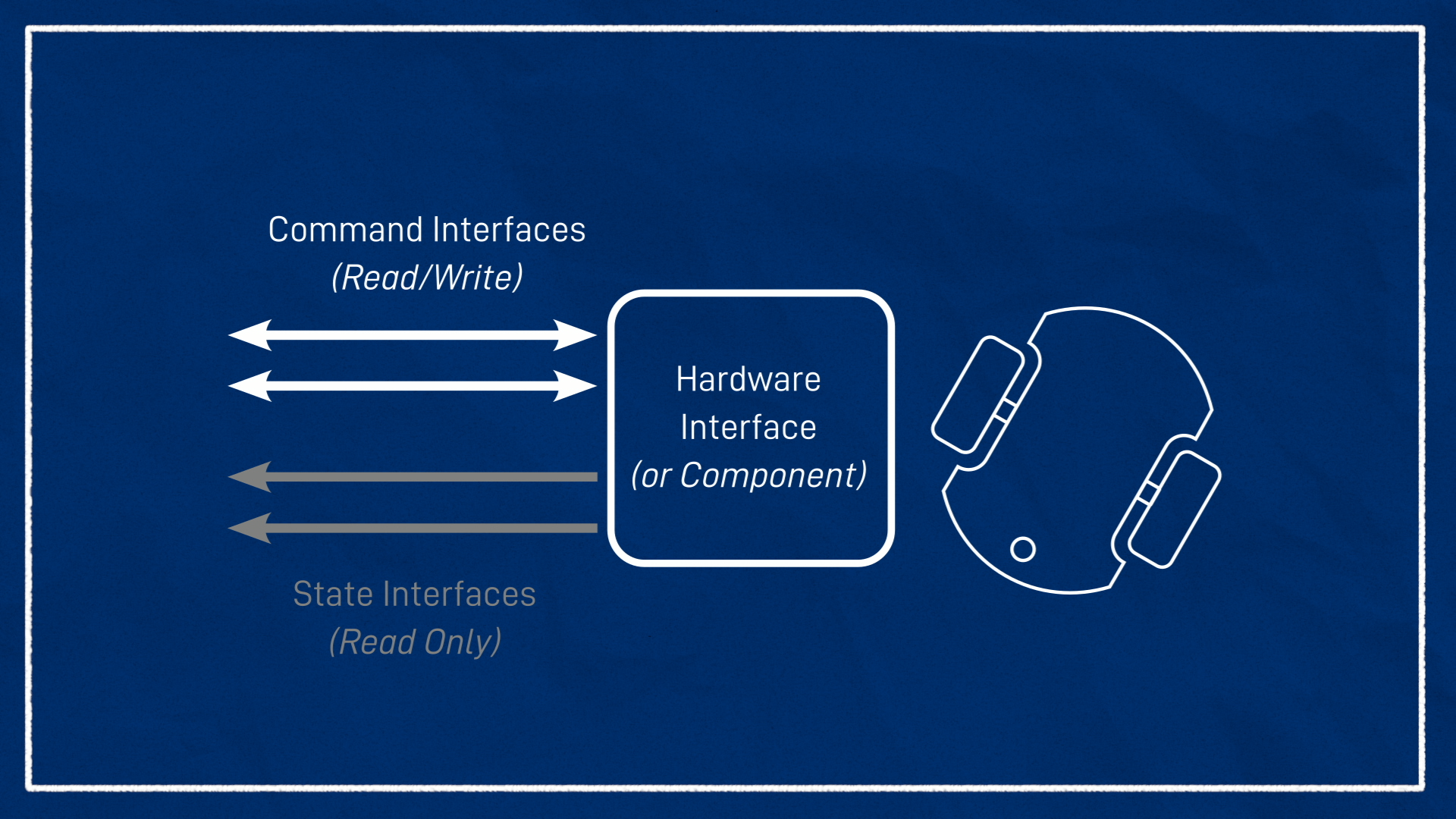
As an example, on the robot I'm building the only thing we can control is the velocity of the motors, so my hardware interface will have two command interfaces, both velocity control, one for each motor. And what state interfaces will it have? Well, using the encoders we can measure both the velocity AND the position of the wheels. So it will have four state interfaces, position and velocity for each motor. If we had other things to measure like torque or current (or even a non-motor sensor like battery level) these could be added in too.
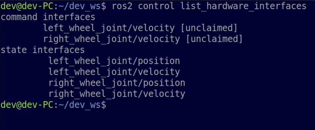
Below is a preview of what we’ll see later on. With the hardware interface loaded, we can see the two command interfaces and the four state interfaces. At this level of abstraction, there is really no understanding of what the robot is. It doesn’t matter if this is a two-wheeled diff drive robot, or a 2 degree of freedom robotic arm that is for some reason only speed controlled - all we see are these six interfaces.
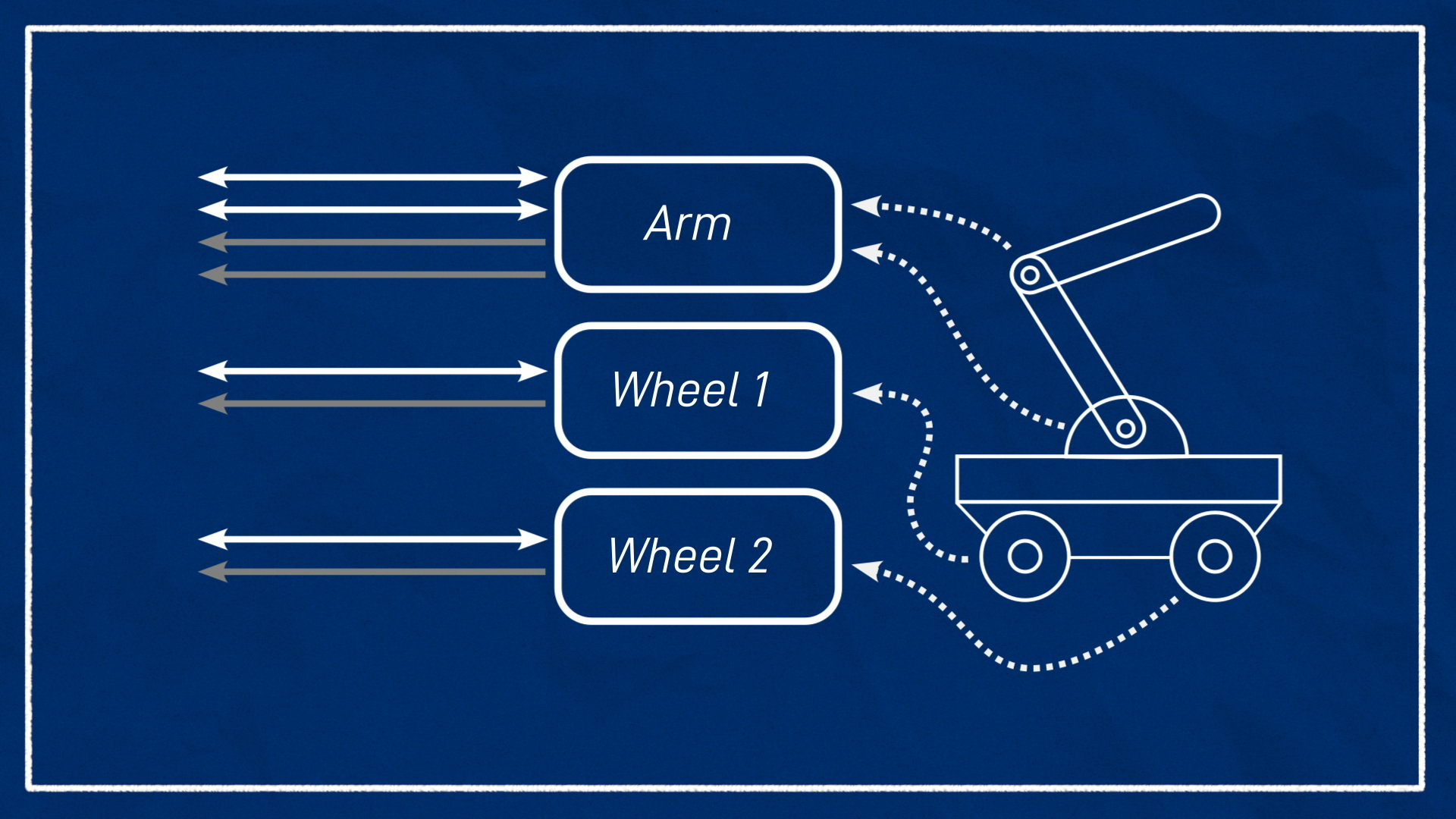
One robot may have multiple hardware interfaces, each of which can have multiple command and state interfaces. There are many reasons you might have this - perhaps you have a robot arm mounted on a mobile base, each with separate motor control systems, or perhaps each of your motors is fully independently controlled with their own driver instance.
To deal with this, the controller manager uses something called the resource manager which gathers up all the hardware interfaces and expose them all together, so the controllers just see a big list of command and state interfaces.
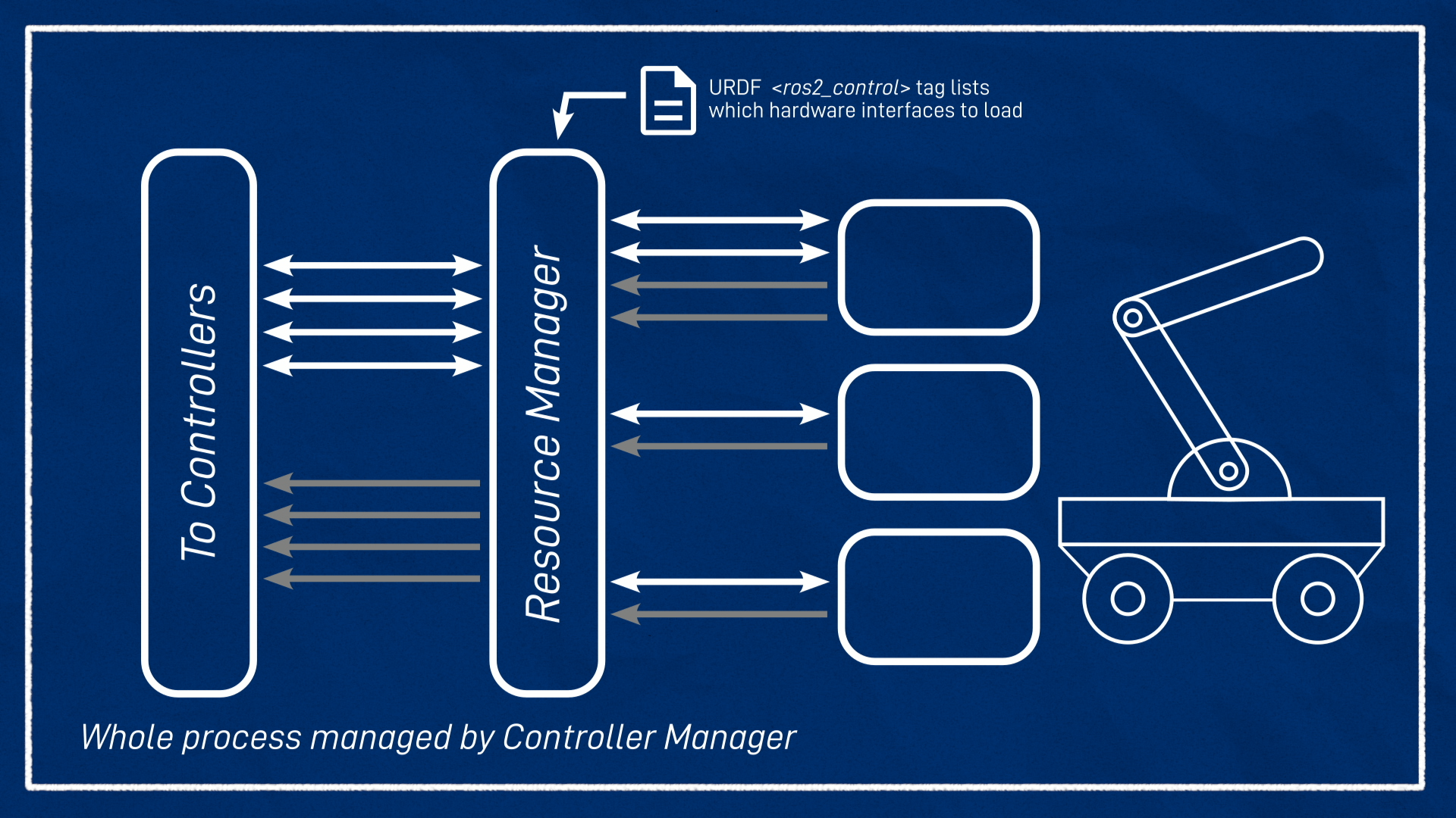
And how does the controller/resource manager know about the hardware interfaces? Because they’re tied pretty closely to the robot’s hardware design, we put it into the URDF using a <ros2_control> tag. We’ll take a closer look at this later.
So that’s the hardware interfaces, what about the controllers?
Controllers
The controllers are how the rest of the ROS ecosystem interacts with ros2_control. On one end they’ll be listening to a ROS topic for control input - could be joint positions or mobile body velocities - they take this input and use some kind of algorithm to figure out the appropriate actuator speeds, positions, etc, and send that to the appropriate hardware interfaces. They can also publish to ROS topics for command feedback or state information they receive from the hardware, and a single controller can pass information in either or both directions. This last point can be a little confusing - it's common to have a controller that doesn't actually "control" anything, it just publishes sensor/feedback data.
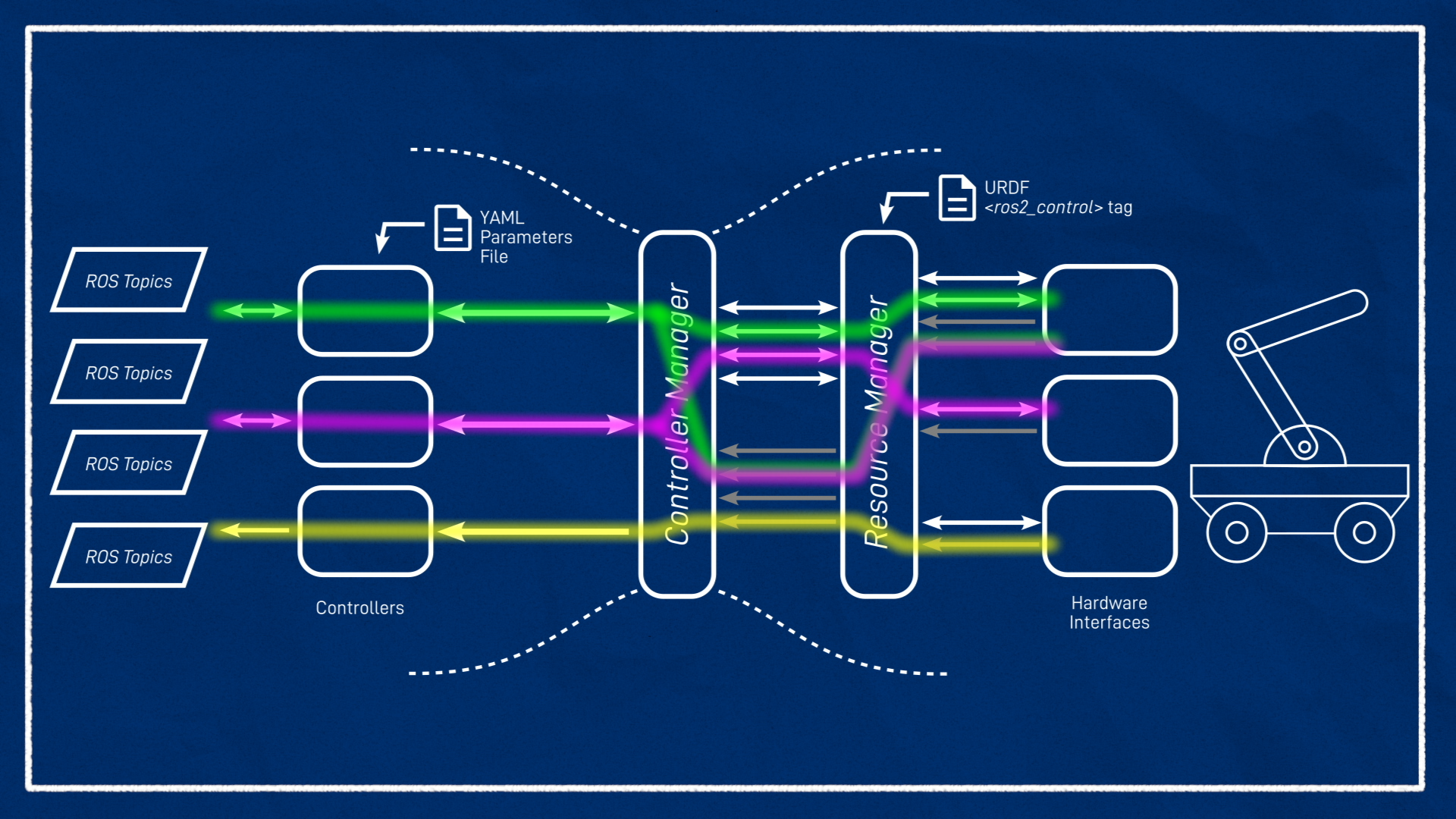
Here the controller manager’s job is to take the controllers it’s asked to load, and match them up with the right command and state interfaces that the resource manager is exposing. To set up the controllers we write a YAML file with the various parameters we need, and pass that in to the controller manager. Once this is all loaded up, we can tell it to start and stop the controllers as needed.
Just like we can have multiple hardware interfaces, we can also have multiple controllers in one robot, as long as they don’t both want to claim the same resources, they’re not trying to command the same (or similar) interface. They can share state interfaces though, since they’re read-only.
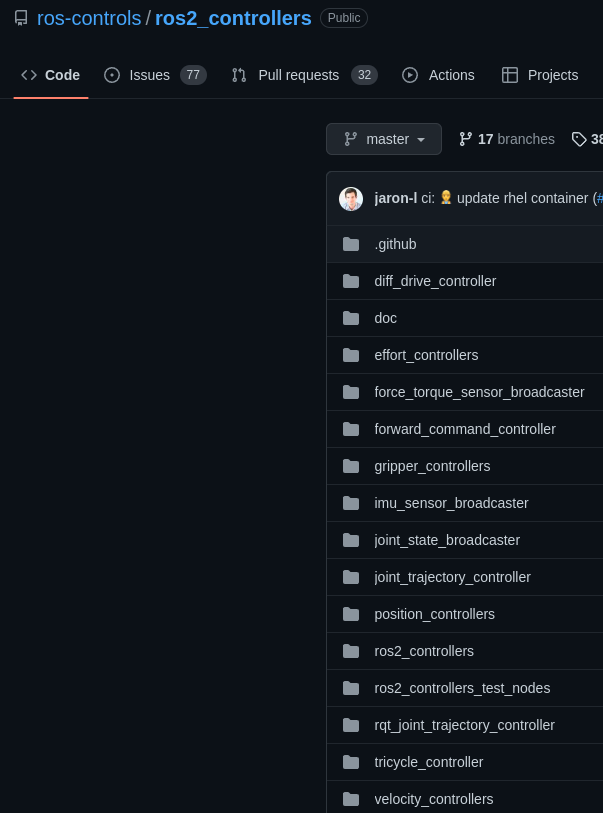
While the hardware interfaces are going to be made specifically for different robot hardware, the controllers are going to be dependent on the robot application, and since there are a few common applications, the ros2_controllers package provides a bunch of controllers that should cover most people’s needs. The project we are working on in these tutorials is a differential drive robot, so naturally we'll be using the diff_drive_controller, but of course a robot arm or something else will require a different controller. And if there isn't an appropriate controller available, we can write our own!
Note that while the primary controller we'll be using in this project is the diff_drive_controller, we'll actually be using a second controller - a joint_state_broadcaster. This controller is one of those "non-controlling" ones and is used to ensure our wheel transforms are generated correctly. More on this later
Running the controller manager
Ok, so we know we’ve got our hardware interfaces on one side, our controllers on the other side, and a controller manager in the middle. So how do we run this thing?
There are kind of two ways to run a controller manager. The normal (and simpler) way to do it is with the ros2_control_node provided by the controller_manager package, but you can also write your own node and instantiate the controller manager inside it. We'll get to see a glimpse of that soon, because the gazebo_ros2_control plugin runs its own controller manager, but when we run it on our robot in the next tutorial we'll learn how to use the standalone one. Either way, we need to provide it with the details of the hardware interfaces (usually via URDF) and the controllers (usually via YAML parameters).
Then, once the controller manager is running, we need to interact with it to do things like checking the hardware interfaces and starting the controllers. There are a few different ways we can do these interactions:
- It exposes some services that we can call
- It provides the
ros2 controlcommand line tool to simplify calling the services - It provides some nodes which will also call the services when they are executed
Using these tools we can start and stop and reconfigure the controllers. Each of methods has its pros and cons which we’ll briefly discuss when we use them later in the tutorial.
Testing it out in simulation
So that’s the theory, let’s start putting it into practice by upgrading our Gazebo robot simulation to use ros2_control!
Installing dependencies
First, we need to install some packages. We want:
sudo apt install ros-jazzy-ros2-control ros-jazzy-ros2-controllers ros-jazzy-gazebo-ros2-control
Update URDF
Now let’s update our URDF - I’ll be continuing the example URDF from the rest of this tutorial series, but it shouldn’t be too hard to follow along if you’re just joining in.
First up we want to:
- Create a new file called
ros2_control.xacrowith our usual<xml>and<robot>tags. - Comment out the old
gazebo_control.xacroinclude and add a new one forros2_control.xacro.
1
So what needs to go in our new ros2_control.xacro file? For now, we’ll have two main tags. There is a <ros2_control> tag, which will have the details of the hardware interface (for the controller manager) and then a <gazebo> tag which will tell Gazebo to load up the extra code that it needs.
First up we’ll fill in the ros2_control tag. We need to give it a name, I’ll call mine "GazeboSystem", and set the type, which is "system". The other types are actuator and sensor which can be used when the hardware is a single actuator or sensor, but system is the most general.
Inside this, we add a <hardware> tag with a <plugin> tag inside that, and this is going to be the name of the hardware interface it needs to load up. This is a piece of code that has been installed and registered with ROS separately, that will talk to Gazebo just like a normal hardware interface talks to a motor controller. In this case, the name of the plugin we want to use is gazebo_ros2_control/GazeboSystem, so we can put that in there.
1
Now we need to specify which joints are to be controlled, so we make joint tags and set the name - in this case the joints that go from the base to the left and right wheels. We also need to declare which interfaces are being made available for that joint. As we saw earlier, we’re going to have one command interface for each wheel (velocity) with the option of specifying limits, and the two state interfaces (velocity/position).
1
That’s the ros2_control tag done, we’ve told it the hardware interface to load and which joints to associate with. Now we need to set up the <gazebo> tag.
It begins similarly to gazebo_control.xacro, inside our <gazebo> tag we have a <plugin> tag. This time the plugin file name is libgz_ros2_control-system.so and the plugin name is gz_ros2_control::GazeboSimROS2ControlPlugin. This plugin is actually doing a few different things:
- Loading up the stuff needed on the Gazebo end to talk to the hardware interface
- Running a controller manager
- Finding the URDF provided by
robot_state_publisher
Because it has the controller manager inside it, it still needs a YAML parameters file to know which controllers to load. To tell it, we need to add a tag called <parameters> and this will be the path to our YAML file. Since we don't have that file yet, just leave it blank and we'll come back to it soon.
1
Controller Config
Up in our config directory, let’s create a new file in our config directory called my_controllers.yaml. This file will be a fairly typical ROS parameter file, if you’re familiar with them.
The first thing we need parameters for is the controller manager. Two simple parameters to set are the update_rate which determines the rate the controllers will update at, and use_sim_time because we want to use this with a Gazebo simulation.
More confusing are the parameters that determine our controllers. We set the parameter name as the name we want to call our controller, then nested under it is the type of the controller. We need to make two controllers, a diff_drive_controller and a joint_state_broadcaster which we'll dive into next. I've named them diff_cont and joint_broad to keep things shorter.
1
Directly below the controller_manager section, we add sections for the parameters of our controllers. The diff_drive_controller has many different parameters to explore, but for now we'll just set the ones below.
The joint_state_broadcaster simply uses the wheel encoder positions to publish the /joint_states message that robot_state_publisher needs to generate the wheel transforms. For a mobile robot this is not all that important - we care more about the position of the robot in space than exactly how far each wheel has turned - but it is still nice to have. For a robot arm it is much more important. I have left its parameter block commented out as we won't be setting anything.
Note that we aren't setting use_sim_time on the controllers - it gets propagated down from the controller manager.
We don't have any parameters to set for joint_broad right now, but I've left space for them (commented out) for the future.
1
Once we’ve finished our controller config, we can go back to our URDF and put in that URL. To get the path to work nicely we can use a neat trick to “find” our package and then specify a relative path. Remember to replace my_bot with whatever you've called your package!
1
Starting the controllers
We can rebuild with colcon to add our new file, then launch our sim just like in the other tutorials - we won't be able to drive any more though. You might notice that the Gazebo terminal is printing out some slightly different content.
This is a good chance for us to start using the ros2 control command line tool. If we type ros2 control and hit tab we can see all the options. The only one we’ll use right now is list_hardware_interfaces and sure enough, we can see our hardware interfaces.
It’s tempting to run list_controllers too, but (as far as I can tell) this will only work once the controllers have been “loaded” - so let’s do that now.
As mentioned earlier, there’s a few ways we can do this. We can use the service call (which is fiddly), we can use the load_controller command we saw a second ago (which is good, but the syntax changed slightly between foxy and the newer versions, and also it’s trickier to use in launch files) or we can use the provided spawner script/node.
Let's try the spawner script. Note that by default the diff-drive controller expects a different cmd_vel topic so we need to remap it to use /cmd_vel.
ros2 run controller_manager spawner diff_cont --controller-ros-args "-r /diff_cont/cmd_vel:=/cmd_vel"
ros2 run controller_manager spawner joint_broad
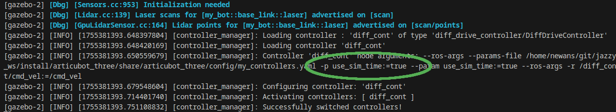
This should provide some feedback to let us know it started succesfully:

And similarly we should see an indication on the Gazebo tab that it started, and automatically sets the use_sim_time parameter (twice, apparently?):
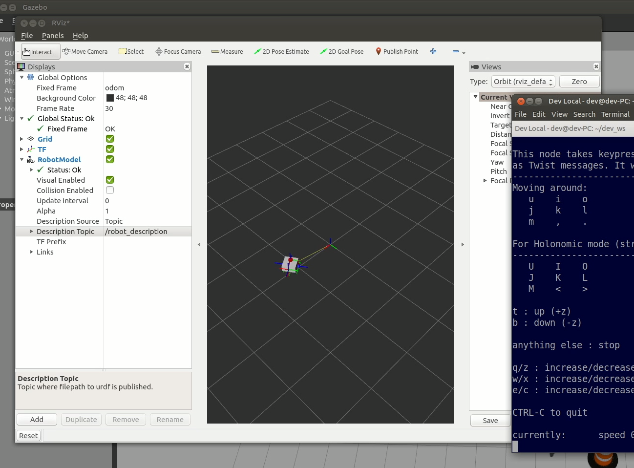
We can now run teleop again (ros2 run teleop_twist_keyboard teleop_twist_keyboard --ros-args -p stamped:=true -p use_sim_time:=true if you didn't already have it open) and drive our robot around, monitoring using RViz.
Updating the launch file
Running those spawner scripts each time is a bit of a pain, let's add them to our launch file (launch_sim.launch.py) so that they start automatically.
1
It's possible to set these up on delays to run after the robot spawner has run (see the version on Github for details), or after a timer, but I have found that there is generally a long enough timeout that it is not an issue. The exception to this is sometimes the first time Gazebo is launched after a boot it can take too long and the spawner times out. In this case you may need to kill and rerun it.
Also this does it more better? https://github.com/ros-controls/gz_ros2_control/blob/8775dbbc9ef537e49bfd1607363d5334ee65dabe/gz_ros2_control_demos/launch/diff_drive_example.launch.py#L103C1-L113C11
Sometimes Gazebo prints an error saying there is no clock source available. I just restart Gazebo and it seems to go away. Let me know if you have a proper fix!
Conclusion
If we drive it around now we'll see that it basically works. If you pay close attention though, you’ll notice there are a few little things that are not quite right. Before we start trying to use this updated simulation or go ahead with the physical robot, it's worth taking these extra steps. I've put them in their own post so if you're following along with the build series, you'll want to head there now.
If you were just wanting an overview of ros2_control, I hope you found this helpful!
If you have other questions or comments, there is a section below where you can join in the discussion over at the forums.