The Transform System (tf2)
Why are Transforms so important?
Coordinate transformations (or transforms) play a huge role in the mathematics of robotics. They are a a mathematical tool to take points or measurements that are represented from one point of view, and represent them in a different point of view that is more useful. Without using transformations, we would need to perform the calculations with trigonometry, which quickly becomes very complex with larger problems, and especially in 3D.
This tutorial is all about how ROS makes using transformations simple. If you're particularly interested in the more complex and interesting underlying mathematics, I've written (most of) a series of tutorials on them, available here.
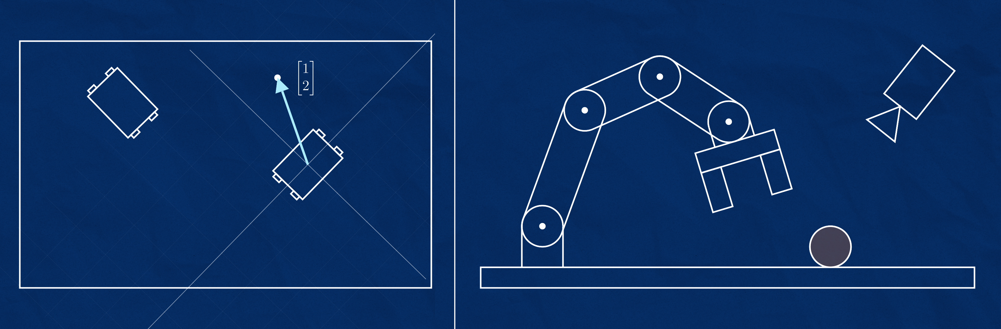
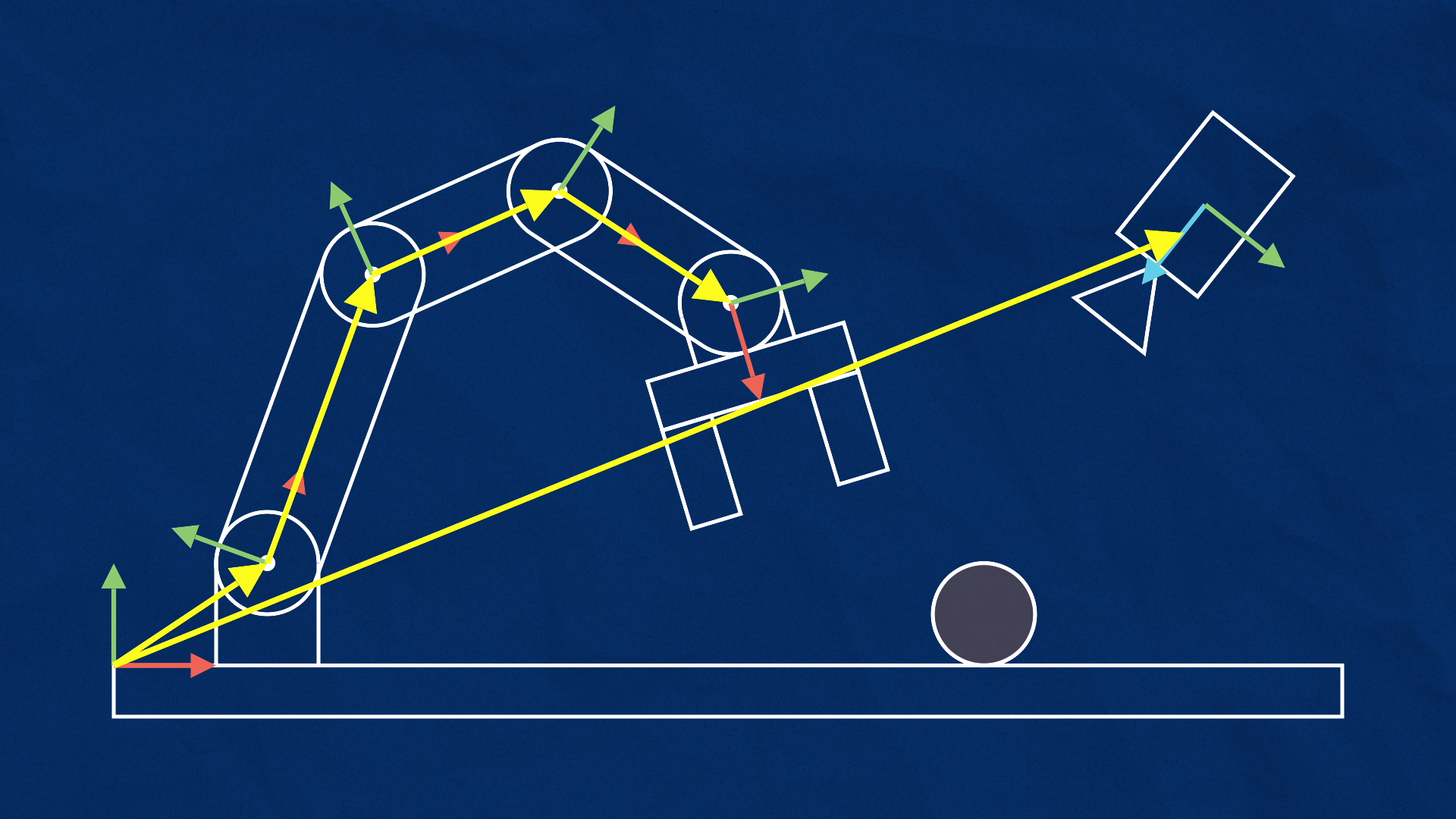
Shown below are two examples of robotic systems where transformations are helpful. In the first, two mobile robots are exploring and one has found an object of interest. How will the other robot know how to get to it? In the second, a mounted camera has spotted a target and a manipulator needs to move the gripper over to it. How do we know the correct motion from the gripper to the target?
To solve these problems, we need to first assign coordinate systems, or frames to appropriate components of our system. Next, we would need to define transforms between the frames. A transform tells us the translations and rotations required to turn one frame into a different frame, and can be easily reversed to go the other way.
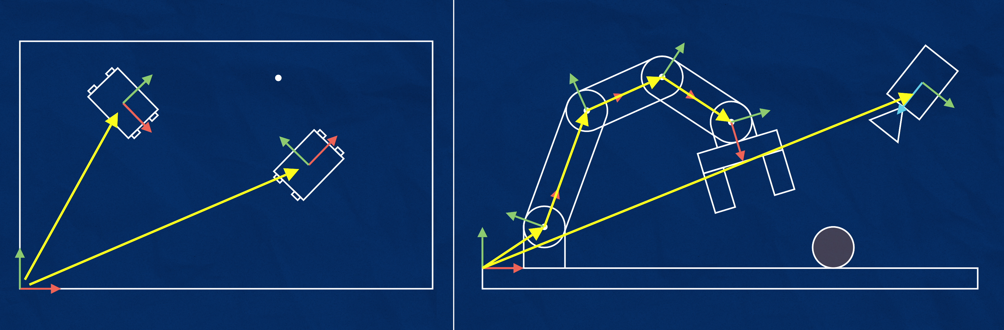
If we have a system where every frame is defined by its relationship to one (and only one) other frame, this will create a tree structure, and we will be able to convert a known point in one frame to any other frame in the tree.
Figuring out all the mathematics and code behind this can be quite tricky, so ROS provides us with a whole subsystem just to make working with transforms easier. In this tutorial we'll learn how to set up a transform tree for some example cases.
Transforms in ROS
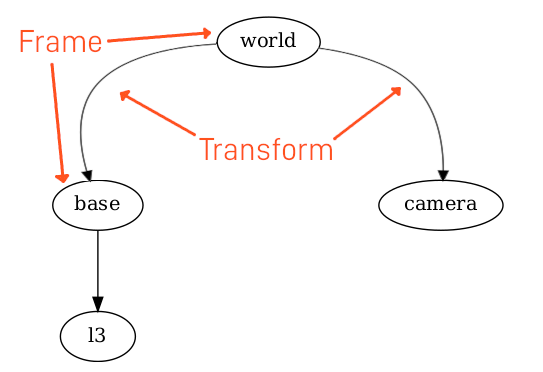
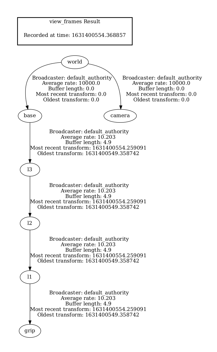
ROS provides a system called tf2 (TransForm version 2) to handle these transformations for us. Any node can use the tf2 libraries to broadcast a transform from one frame to another. As mentioned above, these transforms will need to form a tree structure, where each frame is defined by one (and only one) transform from another frame, but can have any number of frames dependent on it. The picture below shows a portion of a tree that we'll be exploring later. In this tree, base and camera are defined relative to world, and l3 is defined relative to base.
Any node can also use the tf2 libraries to listen for transforms, and then use the transforms to convert points from any frame to any other frame, as long as they are connected in the tree.
When a node broadcasts a particular transform, it can either be static (doesn't change over time), or dynamic (may change over time, but doesn't have to). The reason for this distinction is that robust systems will need to know if their information is out of date, and can flag an error if the broadcaster hasn't updated a dynamic transform for some time. Static transforms, on the other hand, can be broadcast once and are assumed to be correct until a new one is broadcast.
Underneath, the tf2 libraries are still using topics (/tf and /tf_static) to handle all this communication, but because we don't actually publish to the topic ourselves, we call it broadcasting and listening instead of publishing and subscribing.

If we're writing our own nodes, we can code them to broadcast whatever transforms we like, but most of us starting out aren't ready to write custom nodes or calculate transforms. To help with this, ROS comes with some built-in nodes that perform some common broadcasting tasks.
Broadcasting Single Frames
The first way is to manually broadcast them using static_transform_publisher. As you might guess, this tool can't broadcast dynamic transforms, only static ones. That might seem a bit useless, but it's very helpful for learning transforms, doing quick tests, and acting as the "glue" in a bigger system (e.g. if two different nodes expect a frame to have different names, or be in slightly different spots).
The command below will broadcast a static transform, with the translations and rotations provided, from parent_frame to child_frame. Note that the rotations are in radians, and are processed after the translations, in order, with respect to the local coordinate system.
ros2 run tf2_ros static_transform_publisher x y z yaw pitch roll parent_frame child_frame
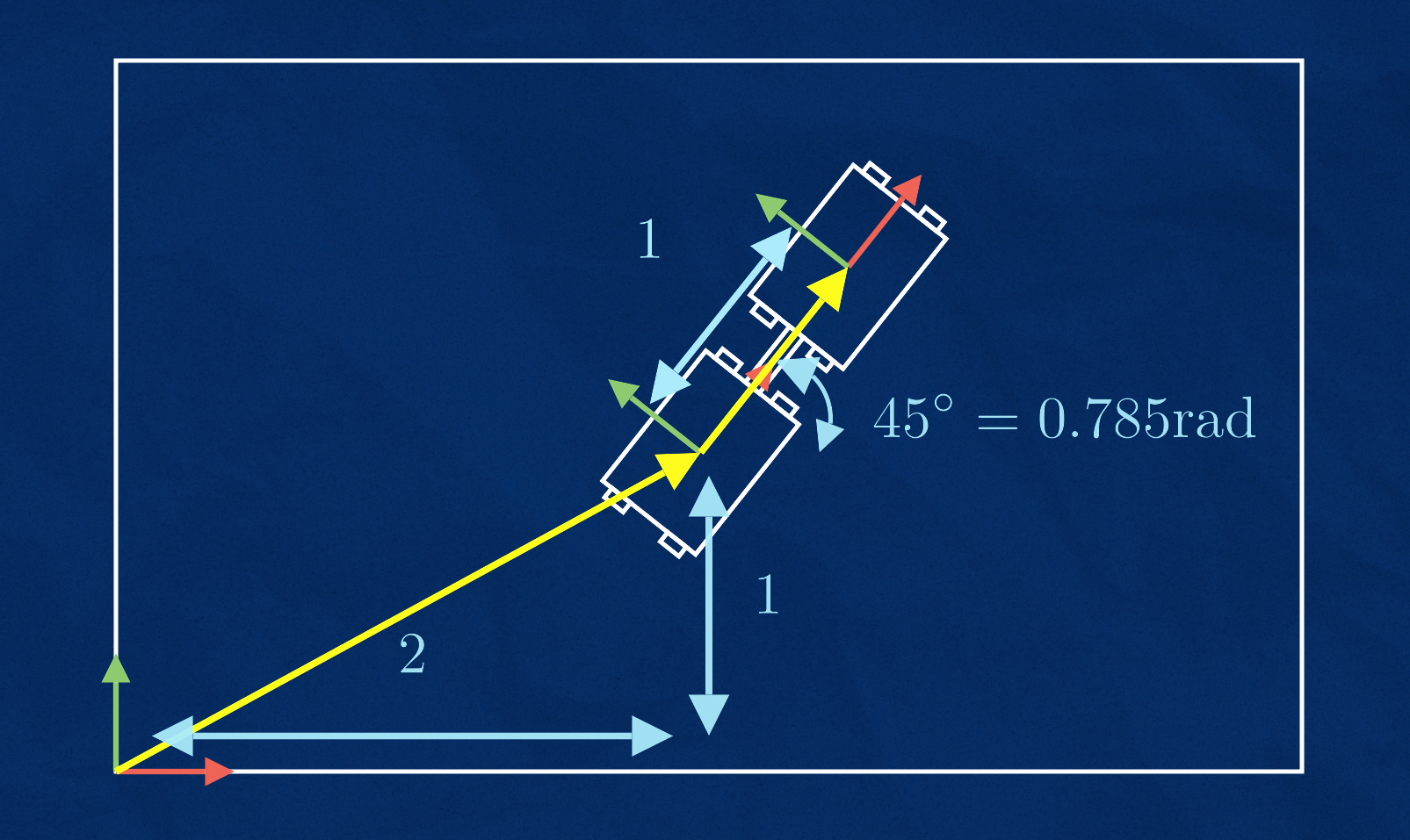
As an example, we might want to have a frame robot_1 that is across and up from a world frame, at a 45° (0.785 rad) angle. To do that we'd use the following command:
ros2 run tf2_ros static_transform_publisher 2 1 0 0.785 0 0 world robot_1
Let's pretend we have a second robot that always sits to the right of our first one (like a sidecar). Using a second terminal, we can create another static transform using the command below to create a new frame, robot_2 that sits 1m in the positive x direction of robot_1.
ros2 run tf2_ros static_transform_publisher 1 0 0 0 0 0 robot_1 robot_2
To check if these worked, we'll use the ROS visualisation tool, RViz.
Viewing Frames and Transforms in RVIZ
In ROS 2, RViz (the ROS visualisation tool) is called rviz2, and is in a package with the same name. So we just need to run:
ros2 run rviz2 rviz2
Note, you can just run
rviz2directly as a shortcut, rather than usingros2 run.
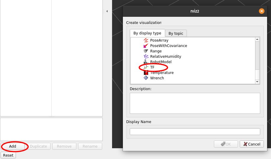
RViz can display all kinds of different data. To display TF data, we click the "Add" button in the bottom-left corner, and select "TF".
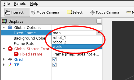
Our transforms won't appear just yet, because we haven't told RViz which frame to use as a reference (it defaults to map, which doesn't exist right now). Up in the top-left corner we can select world as our fixed frame.
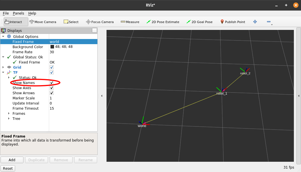
The "Global Status" should become healthy and our two frames should appear, with a line between them to indicate the transform.
Note that RViz represents the transform as an arrow from child to parent, rather than parent to child as in the introduction and in
view_framesbelow.
We can configure the data displayed in RViz using the left panel. For example, we can open up the settings for the TF visualisation and enable displaying frame names.
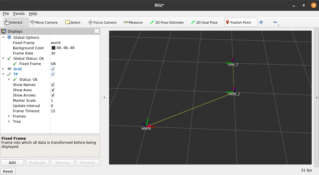
If we go back to our first terminal, and rerun the command with a larger rotation of 90° (1.57 rad), we should see in RViz that the first robot's marker rotates, and the second robot moves too because its frame is defined relative to the first robot.
ros2 run tf2_ros static_transform_publisher 2 1 0 1.57 0 0 world robot_1
It's good to play around with this and get a feel for how transforms work. Try changing the fixed frame (top-left) to be one of the robots instead of world, adjusting the frames to new positions and rotations, or adding some new ones.
We need to make sure to stop all the static_transform_publishers and close RViz before we move to the next part, otherwise they will interfere.
Broadcasting a Moving Robot
We've learnt some cool tricks so far, but we're still stuck publishing static frames. We want our robot to move! Before we tackle this we need to install a couple of extra packages:
sudo apt install ros-foxy-xacro ros-foxy-joint-state-publisher-gui
The first step in doing this is to make sure we have a URDF file for our robot. This is a kind of configuration file where we can specify all sorts of physical characteristics of the robot's components, such as their size, shape, colour, and more. There are many tutorials available for writing URDF files, but for now we can use this example file which is for a manipulator similar to the one from the introduction.
In URDF, a robot is made up of a series of rigid components called links, and the links are joined together in a parent-child tree structure, where the relationships between different links are called joints. Seem familiar?

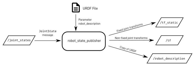
It's not too hard to see how the link/joint pattern is very similar to the frame/transform pattern. Because they are so tightly related, there is a ROS node called robot_state_publisher which can take in a URDF file and automatically broadcast all the transforms from it. It will also publish the full contents of the URDF file to the topic /robot_description so that any other nodes that need it can all use the same file.
In the URDF file each joint can be defined as "fixed", or one of a variety of movable types (e.g. continuous spinning, limited rotation, linear sliding). For the joints that are fixed, robot_state_publisher can just publish a static transform, but for the ones that move it needs an external value (e.g an angle or distance) to calculate the dynamic transform for that point in time. To get these values, it subscribes to a topic called /joint_states, which will contain JointState messages. These messages can contain information about the position, velocity, or effort of a joint (but for now we will only use position).
Suddenly our job got a whole lot easier! Instead of having to broadcast whole transforms, all we need to do is publish JointState messages. Normally, this data will come from actuator feedback sensors on the robot such as encoders or potentiometers (and in a simulation environment those can be simulated). For now, we will just fake the joint states using a tool called joint_state_publisher_gui. This node will look at the /robot_description topic published by robot_state_publisher, find any joints that can be moved, and display a slider for them. It reads the values from these sliders, and publishes them to /joint_states.

Let's have a go at running all this.
First we'll run robot_state_publisher, which can be a bit confusing when doing it for the first time as passing in the URDF file in is a bit tricky. The URDF is taken on the parameter robot_description, so the command will look something like:
ros2 run robot_state_publisher robot_state_publisher --ros-args -p robot_description:=(something here)
You might expect the robot_description parameter to be a path to a URDF file, but it actually expects the full content of the URDF file to be passed in at the command line. To achieve this we need to use the xacro software on the URDF to preprocess it, run that inside a subshell ($(...)), and enclose it in quotes ("...") so that the spaces don't break everything. So our run command will look more like:
ros2 run robot_state_publisher robot_state_publisher --ros-args -p robot_description:="$(xacro path/to/my/xacro/file.urdf.xacro)"
Because it is such a pain to run robot_state_publisher this way, it is generally easiest to create a launch file to do it for us. An example one is available here.
Then, to publish the joint states, we can run
ros2 run joint_state_publisher_gui joint_state_publisher_gui
Finally, we can launch RViz again, add the TF visualisation, and see our frames move as we adjust the sliders. We can also add a "RobotModel" visualisation in RViz. Use the options to select /robot_description as the topic, and a visual representation of the links should appear.
Note, For the case of a mobile platform, things will get a bit more complicated.
robot_state_publishercan broadcast all the transforms within the robot, but you'll need other nodes to publish transforms such as the robot's location within the environment. There are existing nodes to handle this kind of thing, but they'll be covered in later tutorials.
Under the hood
Hopefully the above example worked, but sometimes when we're working with transforms things aren't working properly and we need to figure out why.
As mentioned earlier, the transform data is published across two topics, /tf and /tf_static. We can try to listen to these topics directly using ros2 topic echo, but that can sometimes be tricky to interpret. To help, ROS comes with a tool (do we need to install tf2_tools?) called view_frames that lets us visualise the transform tree, along with information about how it is being broadcast.
Note, in ROS 1 there was a useful tool called rqt_tf_tree which did exactly this but with less hassle. At time of writing, however, this hasn't been ported to ROS 2, and so we have to use view_frames instead.
The view_frames tool is actually a Python script which listens to the transforms for a few seconds, then generates a file called frames.pdf (and also frames.gv) in whatever directory the terminal was in when the script was executed (for a fresh terminal this will be your home directory).
The script is part of the tf2_tools package, so all we need to do is run:
ros2 run tf2_tools view_frames.py
If we take a look at the resulting file (either opening in a file browser, or from the terminal with atril frames.pdf), we can see the tree visualised. Note that the arrows here are reversed compared to RViz (and are the same as in the introduction). We won't worry too much about the rest of the information displayed for now.
If you're not familiar with it, the big numbers starting with "16314......" are times, represented in "Unix Time" which is commonly used in Linux systems, and so in robotic platforms. For more info on Unix Time (a.k.a Epoch Time) check out the Epoch Converter. When running simulations, Gazebo will generate its own time source, and the numbers will be in seconds since Gazebo was started.
Conclusion
The ROS transform system is a powerful tool and we've only just scratched the surface of how we can use it. The details of how we use TF will depend on many factors such as whether our robot is mobile, or a manipulator (or a mobile manipulator), and whether we are running simulations or on physical hardware. In future tutorials we'll look more closely at how TF can be used for particular projects.