Power Concepts
In this tutorial we’re going to look at all things power, and hopefully cover everything you'd want to know about powering a robot.
The principles in this post will apply to all kinds of different robots, but since this is also part of a bigger series on building an autonomous mobile robot, from start to finish, we'll be using that for all the examples (here's a link to the first entry in this project).
This post will focus on the theory, planning out a circuit on paper and ensuring we understand it all, and the next post will have some practical tips for wiring it up.
Power 101
Before we start looking at our example robot, we should do a quick recap of some of the key concepts when it comes to the theory of power.
When we’re working with electricity and trying to talk about “how much” of it there is, there are three terms we usually use:
| Term I use | Other terms | Unit | Symbol in Equations |
|---|---|---|---|
| Voltage | Potential Difference | Volts (V) | V |
| Current | Amperage | Amperes/Amps (A)* | I |
| Power | Wattage | Watts (W) | P |
*Sometimes you’ll see measurements in milliamps, mA. These are 1/1000 of an amp, so 500mA = 0.5A.
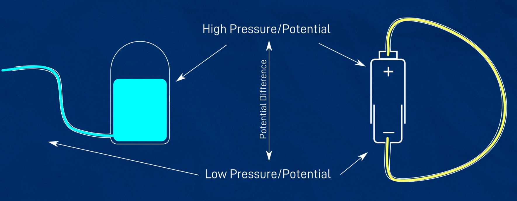
These concepts can be a bit tricky to understand, and plenty of people have tried to explain it over the years (here - are - some videos you can check out). This usually involves an analogy using water pipes, where voltage is the pressure and current is the flow rate. A battery is like a pressurised tank, the energy wants to move from the place of high pressure/potential to the lower pressure zone, but is prevented from flowing. If you connect that tank to pipes, then the pressure will force water to flow through the pipes. The amount of pressure and the size of the pipe (the resistance) will affect how fast the water flows. (Or something like that).
The three things that are probably the most important to understand are:
- Power equals voltage times current (). This means that if you increase either the current or the voltage, you'll increase the power. If you keep the voltage the same and double the current, you’ve doubled the power, if you keep the current the same and halve the voltage, you halve the power.
- For a particular application, the voltage of the device or power supply is usually constant and the current is the thing that changes. For example, until very recently every single USB device out there operated at 5V. But they all use different currents - a wired keyboard might draw a few milliamps, while a USB powered heater (if that exists) could pull a few amps!
- When a power supply gives a current or power rating, that’s the maximum it can safely supply, and when a device or component gives its rating that’s the maximum it will ever use.
That last point is key to many decisions we make as we build our robot. When we exceed electrical ratings, things tend to stop working, get hot, and in the worst cases even catch fire. Our batteries, devices, components, connectors, even our wires all need to be chosen to work safely and correctly together.
Voltages for our robot
To begin with, we’ll choose the voltage for our robot to operate at. We’re actually going to use two different voltages, for different purposes.
5V Power
Firstly we’ll have 5V. Many microcontrollers such as the Raspberry Pi and Arduino are based on a 5V input, and all the USB devices we’ll be using operate at 5V too.
Sometimes you’ll see 3.3V components crop up, we won’t be using them for now but you might want to in the future, since the Pi uses 3.3V for certain things.
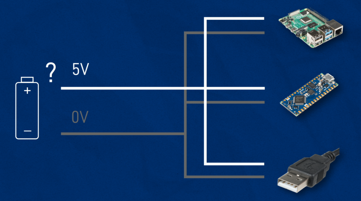
The question is, how do we get 5V? Perhaps a battery? This is where we run into some problems:
- 5V batteries don’t really exist, for chemistry reasons.
- Even if they did exist, they would probably fluctuate in voltage depending on their charge and other factors, and some of these devices need their 5V to be very precise.
- We also need to power our motors, and they'll usually need more than 5V.
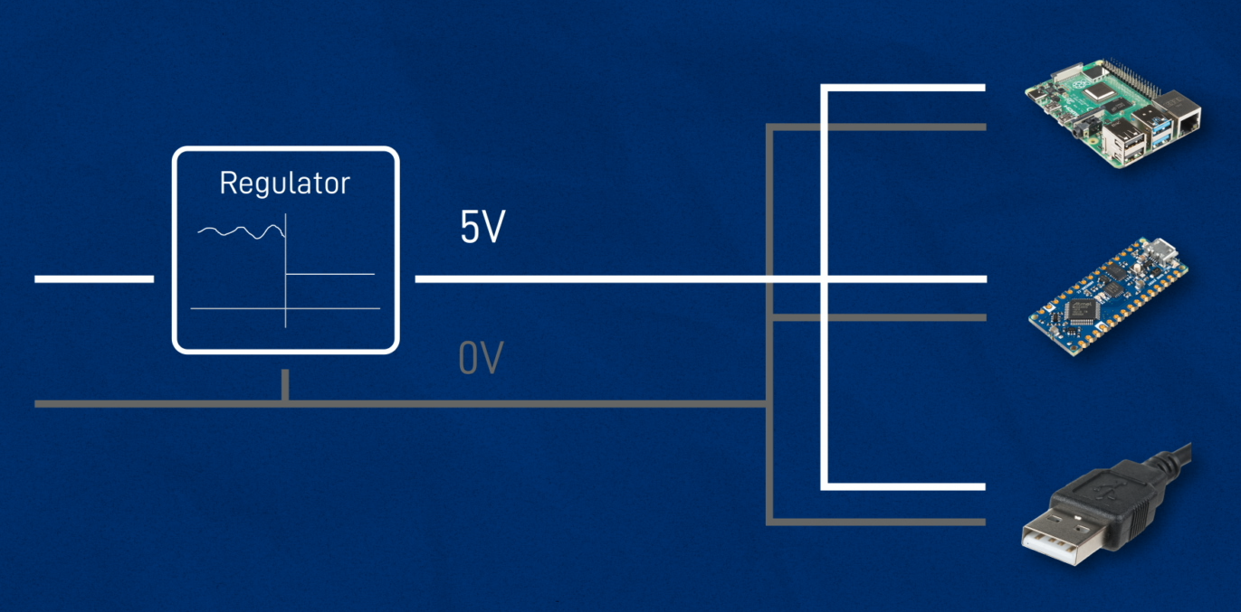
Regulators
The solution, instead, is to use a regulator. This is a component that can take a different voltage (almost always higher, but sometimes lower) and convert it to a precise 5V. It keeps it regular. There are different types of regulators out there, with the two main types being linear and switching.
Linear regulators are simple, small, and cheap. In fact, both the Arduino and the motor driver we’re using include one on-board, just for convenience. They can also produce a nice, clean output. However they are also very inefficient, especially when the input voltage is high and a lot of current is required.
For that reason, in a project like this a switching regulator (a.k.a. switched-mode power supply, or buck converter) is probably more appropriate.
So we know we need a regulator, what will feed into that?
Supply Voltage
Well that’s our supply voltage. In figuring out what it should be, we should ask ourselves whether it will be used for anything else. In our case, we’ll need to supply power to our motors (for me these are DC motors, via a motor driver chip).
So we want the supply voltage to be appropriate for our motors. DC motors are pretty resilient, they can usually deal with a bit of over-voltage, and if we go a bit under they’ll just run slower. My motors are rated for 12V, which is pretty common, but depending on the application you may want to go for 6V, 24V, or something else. If you have a different motor type, things might be a little different, but in any case you should know the voltage you're aiming for.
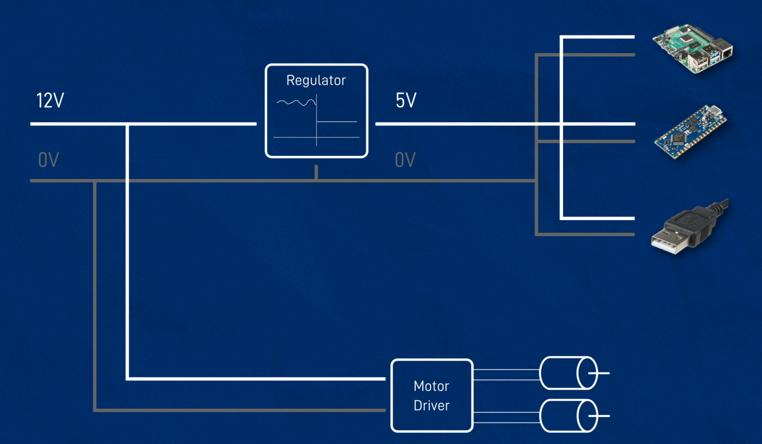
So to summarise our voltages: we have our 12V supply voltage coming in (we’ll see where that comes from later) and a regulated 5V for our components.
Current in our robot
Now that we’ve selected our voltages, we can talk about current. As mentioned earlier, current will dictate a lot of the decisions we make. We might want to aim for lower current devices, to keep things smaller and lighter and minimise battery consumption, or we might want to go for broke and make it big and beefy. Whatever we do, we want to be aware and careful.
Component Current Draw
Let’s start by focusing on our 5V components again. We want to make a list of all the components our robot may have, and get a rough estimate for the maximum current they can draw. For some components this may be difficult, so we just need to make do with what we can.
Disclaimer - these are my estimates, do your own calculations!
| Device | Picture | Estimated Current | Source/Comments |
|---|---|---|---|
| Raspberry Pi | 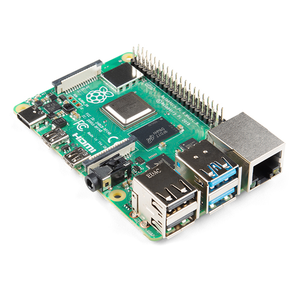 | 1.5A | This page suggests a maximum of 7.3W, although I have seen slightly higher reports elswhere. |
| Arduino | 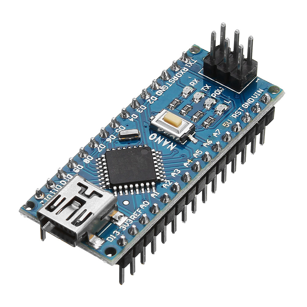 | 0.1A | Various pages such as this one suggest the board itself takes ~30mA, and then extra can be drawn from the pins. |
| RPLidar A1 | 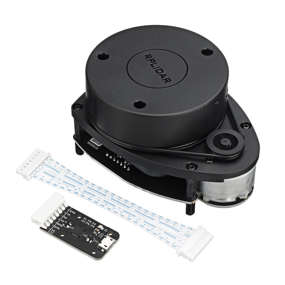 | 1A | Super vague, this datasheet (sourced from here) suggests the laser itself can use 600mA at startup and 350mA when running, with "TBA" for the motor. The A2M7 model suggests 1.5A startup, 2.5A inrush, and 600mA steady state. |
| Pi camera | 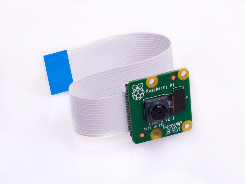 | 0.1A | I've struggled to find anything official, this page has the current with camera as about 100mA extra, but I've seen other reports of 200-250mA. |
| OAK-D Lite Depth Camera |  | 0.9A | According to their page (4.5W) |
| Motor Driver | 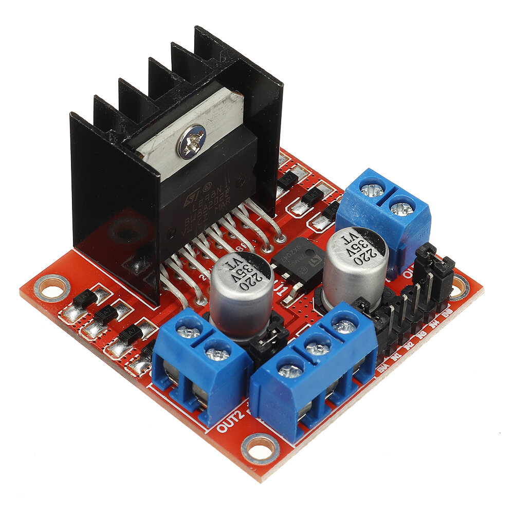 | 0.1A | The actual motor current from 12V will be separate, this is just to run the driver. |
| LCD Screen |  | 1A | This page suggests 1A for the screen I currently have, though I may replace it with a larger one... |
| Total | 4.7A |
I’m going to round it up to 5A total - if you have fewer items (e.g. no depth camera, no LCD screen, no lidar) then your draw will be significantly lower.
Regulator Choice
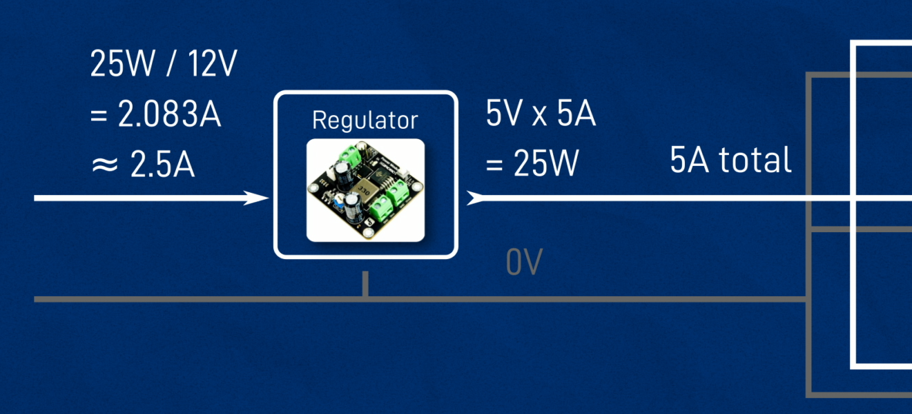
Once we know how much current our 5V components can draw - up to 5A for this example - we need to ensure we choose a regulator that is capable of supplying this much. Even though it’s only passing on power from another source, it still has a limit on how much it can safely let through. So if we need to get 5V at 5A, that’s going to be a total of 25W of power drawn by these components.
I’ll be using this 25W regulator (purchased from here), and we’ll take a closer look at it in the next post when we assemble everything.
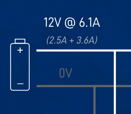
If we want to pull 25W of power out of the regulator, we need to be putting 25W into it - we can treat the whole 5V part of the circuit as one big 25W component. Now, if we were trying to pull exactly 5A out, at 5V, and the regulator was 100% efficient, and we were putting exactly 12V in, then we can calculate that we’d be drawing 2.083A from our 12V supply. In reality though, there will be efficiency losses and we won’t always have exactly 12V since the battery will fluctuate, so we can round this number up to 2.5A to use in future calculations.
Motor current draw
That’s our 5V components, what about our motors?
The motor current draw will be very dependent on the choice of motor and how hard they have to work (how heavy the robot is etc). The more torque they need to put out, the more current they will use - more on this in a couple of posts' time when we set up our motors.
Basically, the worst case scenario is when the motor stalls, which is when the shaft is held still (e.g. because the robot is too heavy) and power is left to run through the stationary motors. That max current draw is called the stall current, and it’ll probably wreck your motor if you do it for more than a moment, so you don’t want to be going anywhere near that.
To find out what the stall current is without breaking things, we can check the motor datasheet. It should tell you the stall current, and probably also some currents at lower torques. Here is the datasheet for the motor I plan to use (it's a bit smaller than what I have used in the past), and you can see it apparently has a stall current of 1.8A, and a rated-load current of 0.75A.
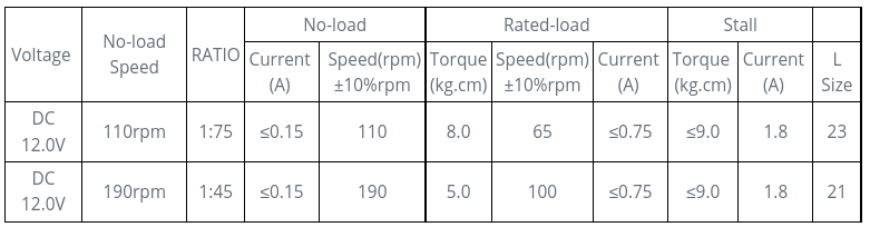
Remember we’ve got two motors, so the total maximum current is gonna be double that - 3.6A in my case. You should also make sure your motor driver is rated for the right amount of current - again we’ll cover that when we look at the motors.
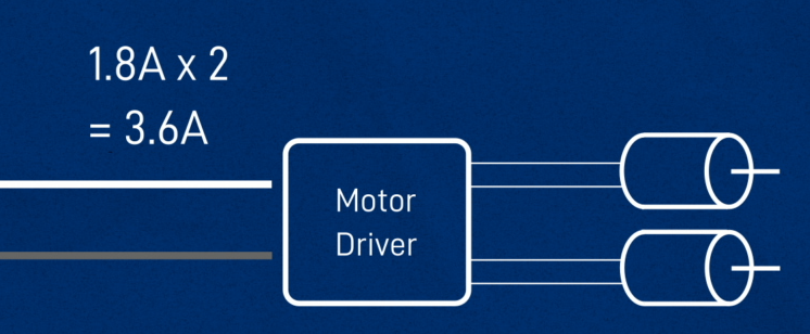
So the total current required for our 12V power supply is about 6.1A. Since this is a mobile robot, that 12V power is going to need to come from a battery!
Batteries & Power Supplies
So how do we choose a battery? Basically, we’re looking for something that is:
- Close to 12V in output
- Can handle at least 6A or so, (2.5A to the regulator, 3.6A to the motors)
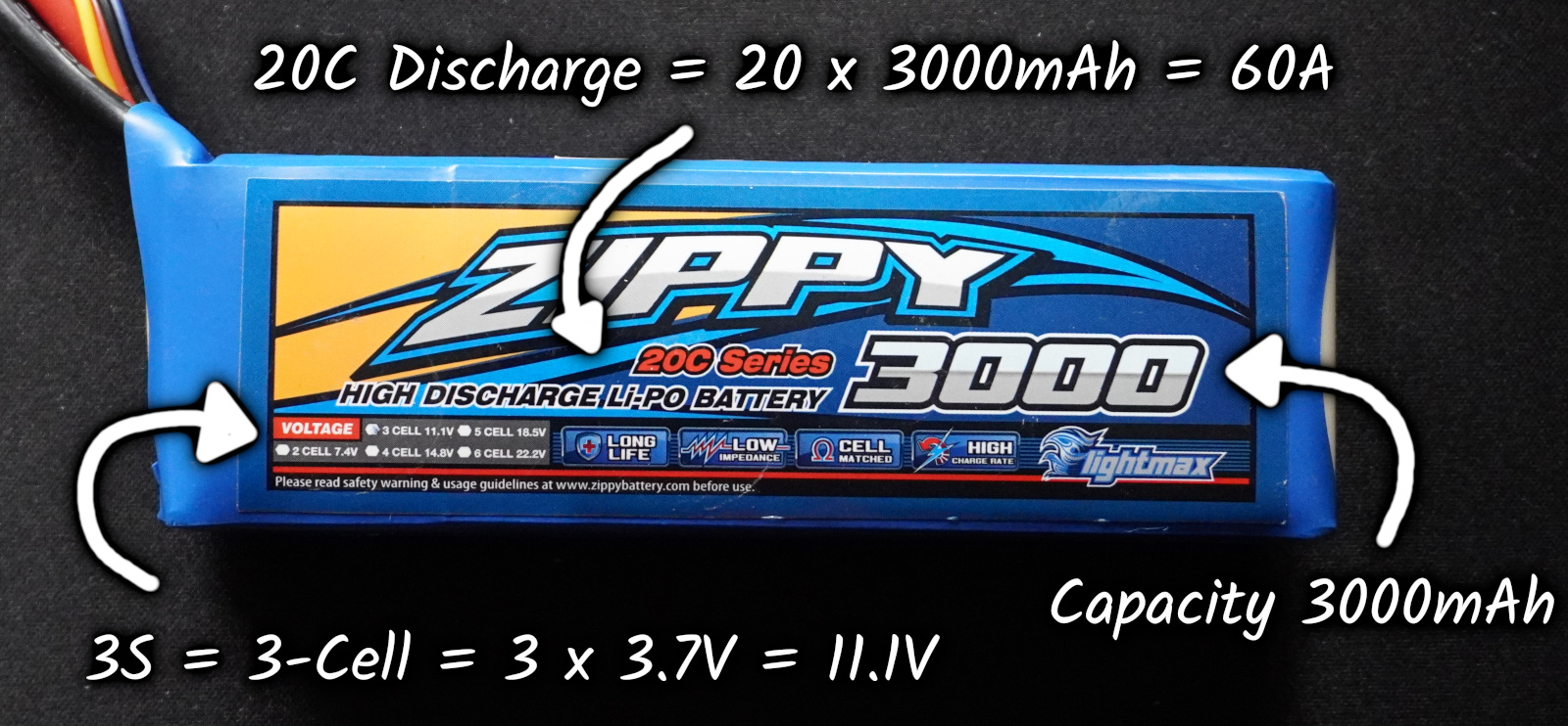
Our most likely candidate is going to be a 3-Cell LiPo. If you’re not familiar with LiPo batteries, here's a video covering a bunch of things including safety (here's another). There are a few important things to know about our battery, and the most important one is a warning.
LiPo batteries pack lot of power and energy into a reasonably small package, which is great for powering a robot, but also poses a safety risk. Whenever you’re working with them you want to be careful. Don’t let the charge get too low, don’t let the wires short on anything, make sure you charge them with a proper charger, in a fireproof area, with the balance leads in, under supervision, store them in a safe container, etc.
-
The S number, is the number of cells in the battery. The battery you buy is actually a bunch of smaller cells joined together to increase the voltage. So a 3S battery has 3 cells.
-
LiPos actually vary a lot in their voltage, depending on how charged they are. Each of our cells has a typical voltage of 3.7V, so for example a 3 cell battery has a total of 11.1V. When they’re fully charged, the total will be closer to 12.6V (that’s 4.2V per cell), and the voltage will drop as we use them. I don’t like to let mine get below 10V, so make sure you check it regularly.
-
The capacity, usually measured in milliamp-hours (mAh). That’s how much current you could continuously draw for the battery to go from full to empty in an hour. If you’re pulling more current, it’ll last less time etc. So a 3000mAh battery could run at 6A, 6000mA, for a half an hour, 30 minutes. You don’t want to run it the whole way down though, aim to use maybe two-thirds of that, keeping an eye on the voltage.
-
The discharge rating, or “C number” tells you the maximum current that can be drawn from the battery. It’s a bit weird, but basically you multiply the capacity by the C number , so this battery is 20C, and 3000mAh, so that’s 60000mA, or 60A (more than 10 times the 6A required for our example circuit).
If you want you can do all your testing using a battery but you’ll be forever recharging it which is annoying. I recommend getting a wall-powered supply. The best option is to get a proper lab power supply, which lets you control the voltage precisely and set a limit on how much current can be drawn.
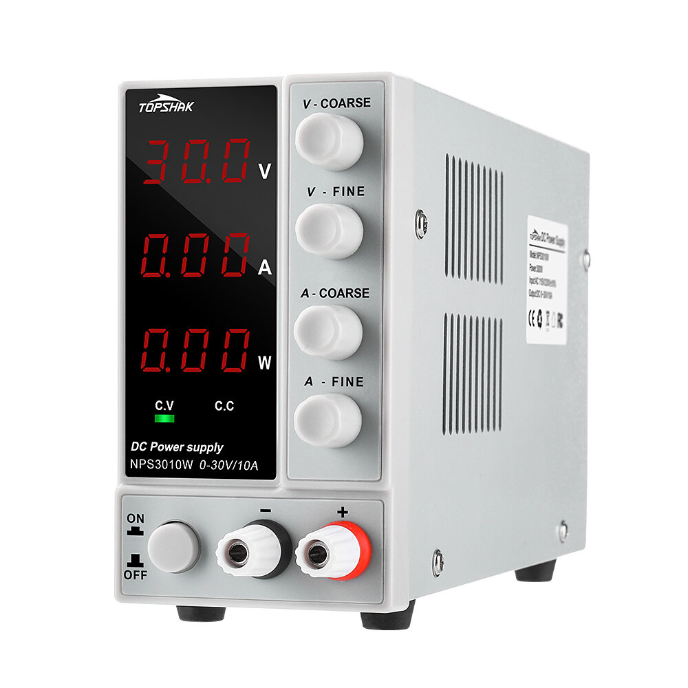
They’re not too expensive , but if you can’t afford it you can use a “wall-wart” AC-DC adapter as long as you check the sticker to make sure the voltage and current are enough (which will be fairly rare), you can get dedicated 12V power supplies, you can modify a computer power supply, or if you’re really stuck you can use a car battery, which is still obviously a battery but won’t drain anywhere near as fast.
Other Aspects
That’s all the main components of our circuit covered, but there are a few other parts of the circuit infrastructure that are important to be aware of before we’re done. These last bits are some of the most important for safety.
Wiring and Connectors
Something to make sure we don’t forget is that all our wiring and connectors need to be able to support our current levels too! And note that I’ve said current, because it actually doesn’t matter too much what the voltage is, the current is what determines how safe it is.
There are many factors that affect maximum wire current, but here is an example of a standard table available to check the current for a particular gauge (thickness) of wire.
For connectors, you'll want to try and find a datasheet or other documentation (e.g. the popular XT60 connector is capable of carrying 60A, while the much smaller RCY connector is rated for 3A).
Related to this is something alluded to in the previous post, that the Pi has a limit on how much current can go through its USB ports, so in the next post I'll cover how to get around this by wiring up an externally-powered USB hub.
Power Switch
Once we’ve got safe wiring, we need a power switch so that we can turn things off when we’re done and not risk any shorts as we plug our battery in and out
Fuse
And the last thing we need to add to our circuit diagram is a fuse.
Without a fuse, if positive gets connected directly to negative somewhere, maybe a loose wire or maybe a component fails, then it creates what’s called a short circuit, and a huge amount of current will flow from the battery, through all the wiring.
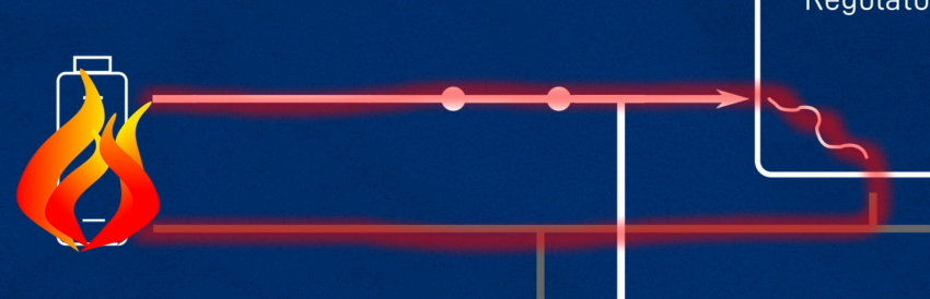
It’ll basically use as much power as it can, and burn out the wiring, or worse, set the battery on fire. That’s generally regarded as something to avoid, so by adding a fuse we are creating a deliberate failure point. If the current is getting too high, it will burn out the fuse and break the short circuit, keeping us safe.

We don’t want it to burn out under normal use though, so we need to choose a fuse that has an appropriate current rating, it will let through current up to a certain level, and burn out if it goes beyond that.
Remember this is only to protect the wiring and the battery, not the other components, they could still be damaged. There are other types of fuses that we could put in at different places to do that, but we’re not going to worry about that for now. In the next post I'll show you the fuse I'll be using.
Conclusion
That about covers it for the theory side of things, in the next post I’ll wire everything up and we can dig a bit deeper on certain aspects of the circuit! If there’s anything particularly important for safety that you think I've missed, please let me know and I can amend the post. Have fun designing a circuit for your robot!