URDF Design
In this tutorial we're looking at the concept design of the robot, understanding the differential drive approach and creating a rough URDF (structural description). The post grew a little too long to include the initial simulation, so we'll cover that in the next one.
Differential Drive Robots
Differential-drive control
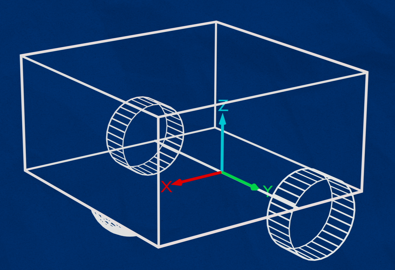
This robot is a differential-drive robot, which means the robot has two driven wheels, one on the left and one on the right. These two wheels control all motion, and any other wheels are just there to keep it stable and can spin freely in all direction (these are called caster wheels). This arrangement is popular for robots as it is simple to understand, build, and control, and is also quite nimble since it can turn on the spot (unlike, say, a car that requires space for a U-turn or three-point-turn).
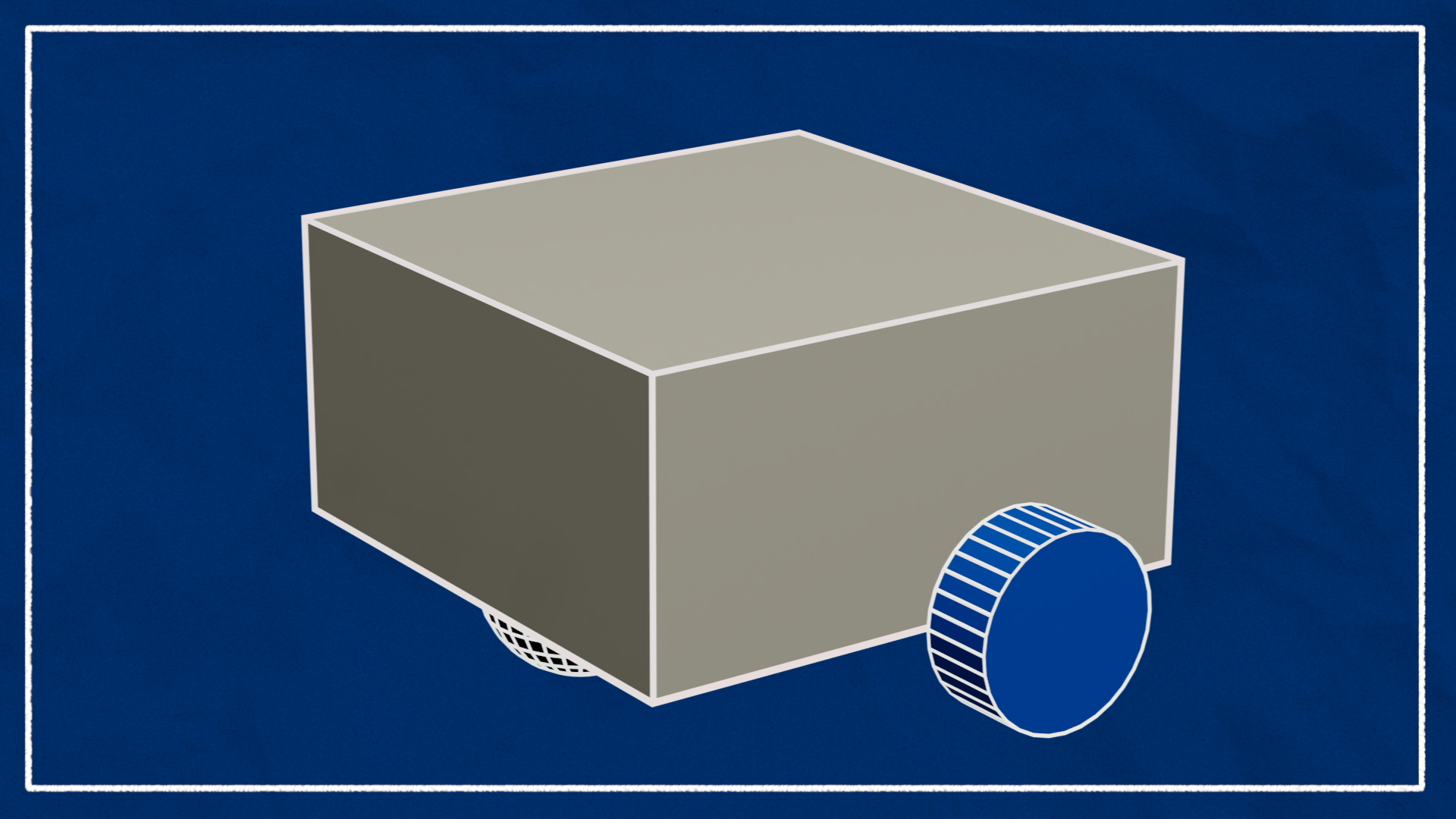
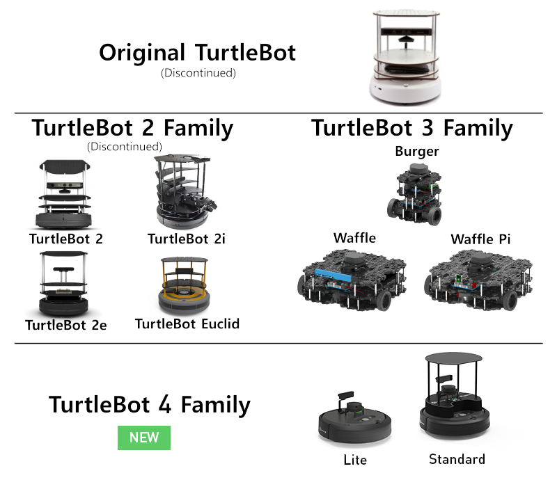
Differential-drive robots can come in a variety of shapes and sizes. For today, I'm going to pretend our robot is a small box, with the driven wheels near the rear and a caster near the front. You may like to design yours a little differently - here are some examples of the various iterations of the "TurtleBot" design, a popular ROS robot for education and research.
Mobile Robots in ROS
Since our robot is a mobile robot we'll be following some of the conventions set out in in the ROS REPs (essentially the standards):
- The main coordinate frame for the robot will be called
base_link(REP 105 - Coordinate Frames for Mobile Platforms) - The orientation of this coordinate frame will be X-forward, Y-left, Z-up (REP 103 - Standard Units of Measure and Coordinate Conventions)
Working With URDF Files
Let's start by covering some basics of how to work with URDF files.
Quick Recap
First, we should recap how to publish a robot description using URDFs. We start off with a bunch of files in the URDF format, that together describe our robot.
These files are processed by a tool called xacro which combines them into a single, complete URDF. This is passed to robot_state_publisher which makes the data available on the /robot_description topic, and also broadcasts the appropriate transforms.
If there are any joints that move, robot_state_publisher will expect to see the input values published on the /joint_states topic, and while doing our initial tests we can use the joint_state_publisher_gui to fake those values.

To make life easier, we typically wrap this up into a launch file.
Before we move on, we also want to make sure that xacro and joint_state_publisher_gui are installed (if they aren't already):
sudo apt install ros-jazzy-xacro ros-jazzy-joint-state-publisher-gui
Launching and Visualising
If you made a copy of the package from the GitHub template repo, you should already have a launch file (launch/rsp.launch.py) and a description directory containing a very basic URDF, robot.urdf.xacro.
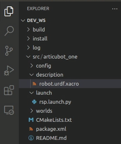
Try launching that file with ros2 launch my_bot rsp.launch.py (where my_bot is whatever you called your package, mine is articubot_one). You should see the output displayed below:
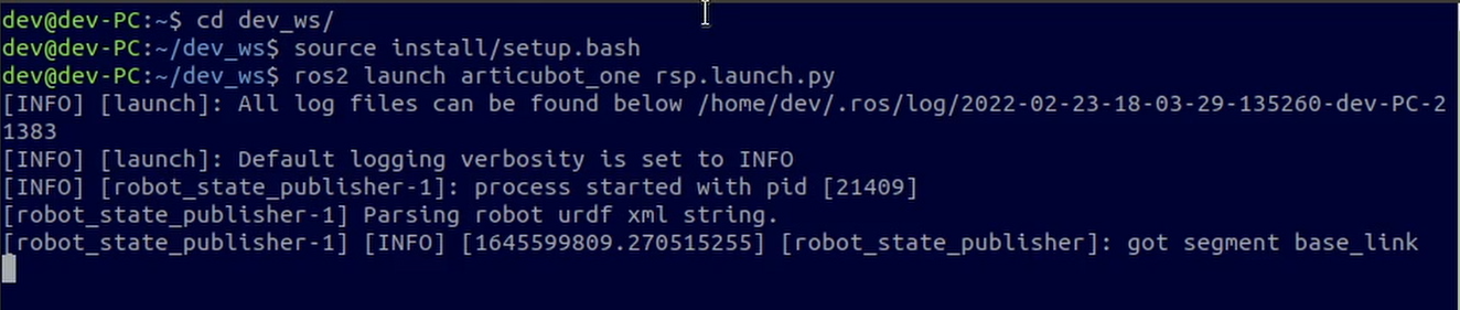
Because this URDF file only has a single link (and it's empty), there won't be anything to display in RViz yet.
Tricks when making changes to URDFs
Before we start creating our URDF files there are a couple of things to be aware of when saving our changes.
- If you build your workspace with
colcon build --symlink-installthen you don’t need to rebuild every time you update the URDF, it will be automatic EXCEPT whenever you add a new file. That file needs to get built/copied once, and after that will be kept updated. - You’ll need to quit and relaunch
robot_state_publisher(orrsp.launch.py) each time you make a change. - RViz sometimes won’t pick up all your changes straight away. In this case you'll need to hit the “Reset” button in the bottom corner. If it’s still not updating, try ticking and unticking the display items, or closing and reopening the program.
Creating our URDF
Now it's time to create a URDF for our robot!
Splitting up our files
For this robot, instead of keeping all our configuration in a single URDF file, we’ll be splitting it up into multiple files and including them in a main file. In this post we'll be focusing on a file that contains most of the core structure of the robot, and later on we will create more files for our sensors etc. and we can include them all in here to keep things organised.
To begin with, open up robot.urdf.xacro from the template and delete the base_link that is currently there. Replace it with the line <xacro:include filename="robot_core.xacro" />, so that your file looks like this:
1
If we try to relaunch robot_state_publisher now, it will fail, because it is trying to include a file called robot_core.xacro that doesn’t exist - so we better make it!
Creating the visual structure
We're about to start creating the visual structure for our robot. Fair warning, we'll start to get into a bit of maths and geometry and spatial stuff here, which can be a bit confusing if you're not used to it. Try to follow along, but if you get confused you should be able to copy-and-paste and muddle your way to the end, and hopefully things will make more sense in hindsight.
Making the Core File
In the description directory, create a new file called robot_core.xacro. To ensure it’s a valid URDF, we’ll start by copying the XML declaration and the robot tags (these are the same as in the previous file but without the name parameter). All of our links and joints will be going inside the robot tag, and we’ll step through them one by one.
1
Colours
As mentioned in the URDF tutorial, we have the option to declare some materials (colours) up-front so that we can use them later. The colours are specified as float RGB triplets with an alpha channel. If that's meaningless to you, don't worry too much. You can start with these colours and if you want more, use this colour picker and copy the values from the "RGB 0.0-1.0 float" section.
You can either put these into a separate file (e.g. colours.xacro, remember to add your robot tags and include the new file), or at the top of this file just inside the robot tag.
1
Base Link
As mentioned earlier, it is standard in ROS for the main "origin" link in a mobile robot to be called base_link. You might think the natural place for the base link is in the centre of the chassis somewhere - and this wouldn't necessarily be wrong - but for a differential drive robot it is simplest to treat the centre of the two drive wheels as the origin, since the rotation will be centred around this point. The rest of the robot can then be described from there. So we start with an empty link called base_link.
1
If you want you can relaunch robot state publisher now and check everything runs (make sure to rebuild the workspace since we added a file).
Chassis
Next up is our chassis. Remember, we're not so interested in the final design right now, just the rough structure, so let's make it a box that is 300 × 300 × 150mm (for our American friends, this is about 1 × 1 × 1/2 ft). URDF values are in metres, so that's 0.3 × 0.3 × 0.15m.
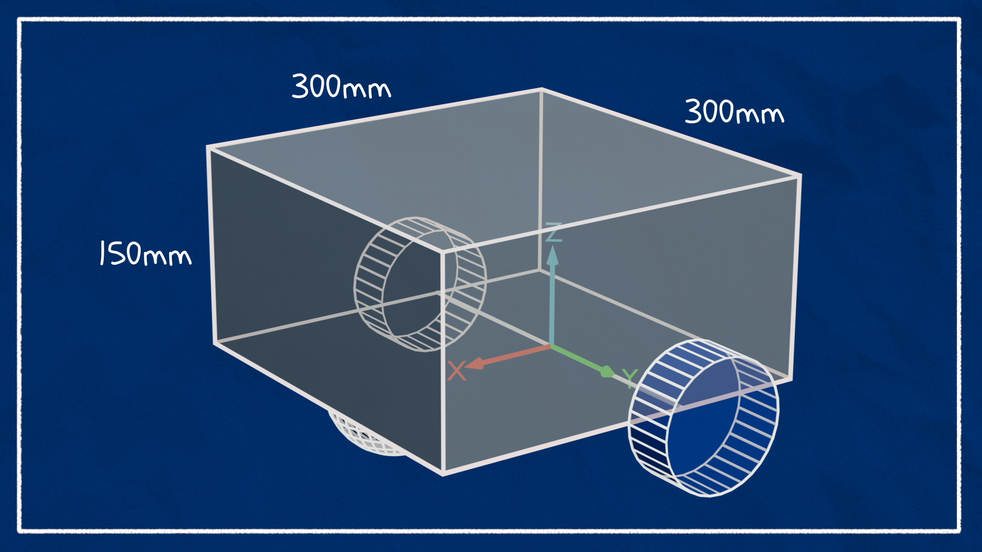
I want the origin (the reference point) of the chassis to be at the bottom-rear-centre. So that means this chassis link will be connected to our base_link via a fixed joint, set back a little from the centre.
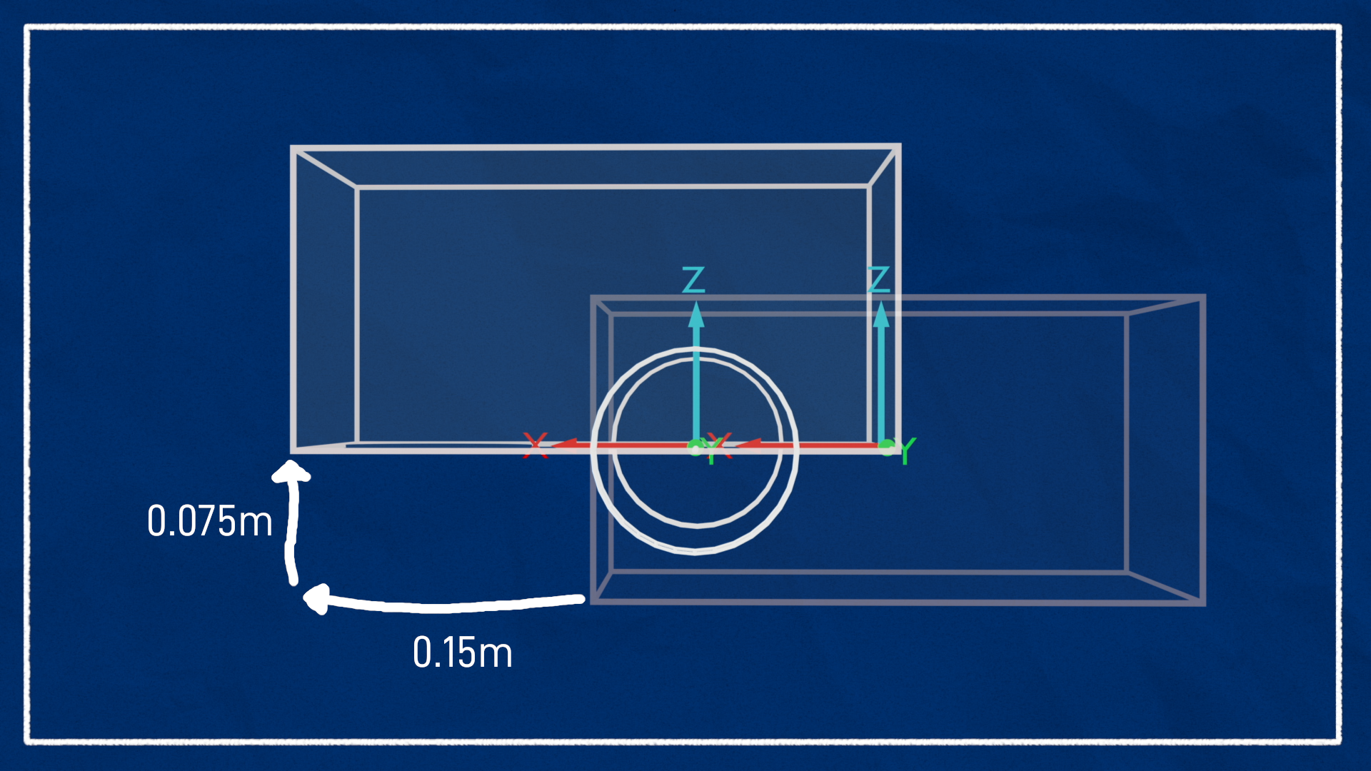
One other thing to note here is that by default the box geometry will be centred around the link origin. Recall that we want the link origin at the rear-bottom of the box, so to achieve that we want to shift the box forward (in X) by half its length (0.15m), and up (in Z) by half its height (0.075m).
1
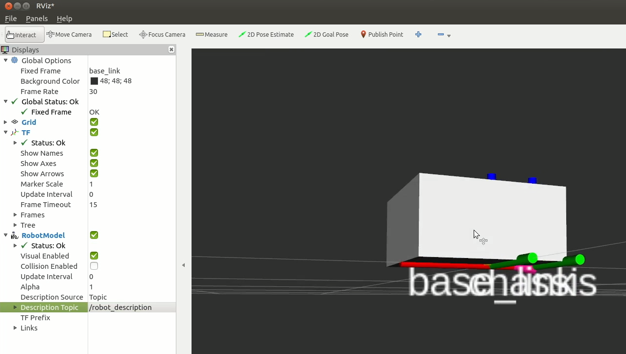
At this point we can relaunch rsp.launch.py and then start RViz in another terminal (rviz2 or ros2 run rviz2 rviz2) to see the transforms and visuals displayed - it should look like the image below.
- Set the fixed frame to
base_link - Add a TF display (and enable showing names)
- Add a RobotModel display (setting the topic to
/robot_description)
If you’d like to save your RViz setup for future use, you can do so in the file menu. Using "Save Config" will override the default, or you can use "Save Config As" to save to a new location. Then to use it, when running RViz you can use the -d argument and the path to the .rviz file. E.g. rviz2 -d ~/path/to/my/config/file.rviz.
If we wanted to, we could skip the chassis step and just add our boxes to the base link, but there are two reasons to do it this way:
robot_state_publisherwill issue a warning if the root link has an inertia specified.- If we have future things physically attached to the chassis (e.g. camera, lidar), by attaching them to a
chassislink we can move the wheels forwards or backwards if required and only change one number instead of all of them.
For our URDF to work properly we also need to add collision and inertia information, but we’re going to get all the visuals sorted out first, and then come back through and add the other stuff.
Drive wheels
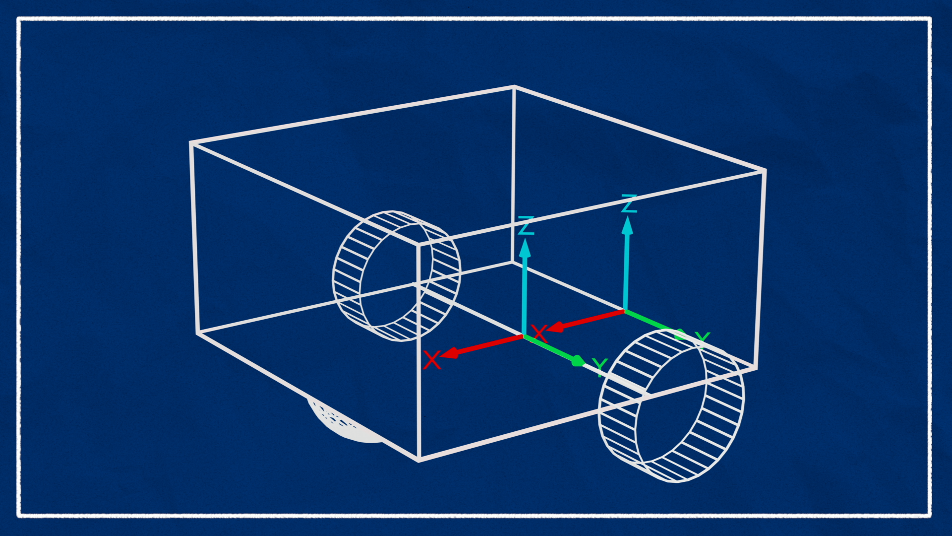
Now we want to add the drive wheels. The wheels can move, so these will be connected to base_link via continuous joints. We could connect them to the chassis instead, but since we chose the base link to be at the centre of rotation it makes sense for the wheel links to be connected directly to it.
We want our wheels to be be cylinders oriented along the Y axis (left-to-right). In ROS though, cylinders by default are oriented along the Z axis (up and down). To fix this, we need to "roll" the cylinder by a quarter-turn around the X axis. I like to keep the Z-axis pointing outward (not inward), so I will rotate the left wheel clockwise (negative) around X by a quarter-turn ( radians), and the right wheel anticlockwise ( radians).

The last item of interest is the rotation axis. Since our left wheel has Z facing out, a "forward" drive would be an anticlockwise (positive) rotation around the Z axis. So we want the left wheel's axis to be +1 in Z.
The full blocks for both wheels (including some chosen values for the cylinder length, radius, and Y offset - how wide the wheels are spaced apart from the centre) are shown below.
1
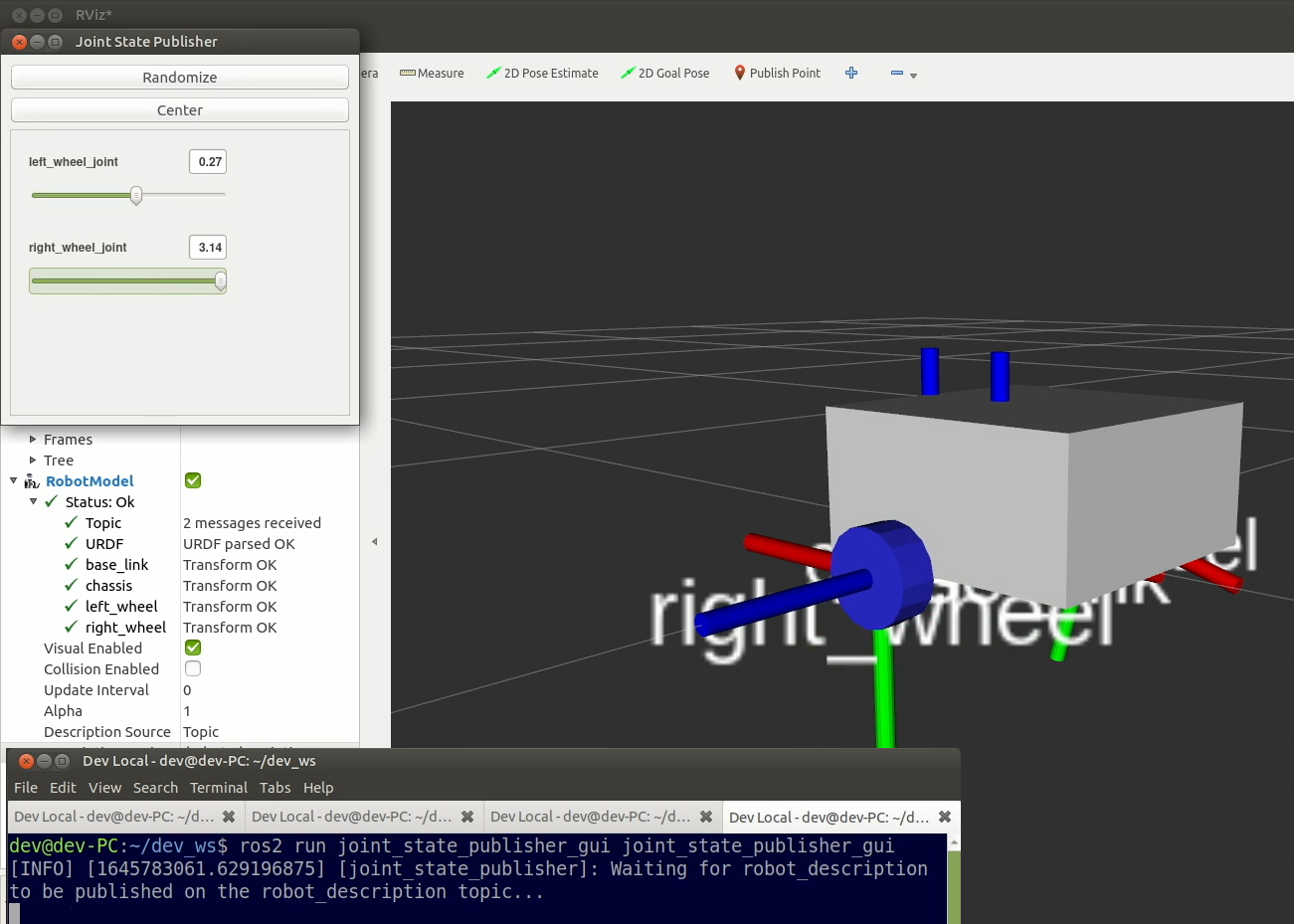
If we try to view this in RViz now we'll notice that the wheels aren't displayed correctly, since nothing is publishing their joint states. We can temporarily run joint_state_publisher_gui to resolve this and see the wheels visualised.
ros2 run joint_state_publisher_gui joint_state_publisher_gui
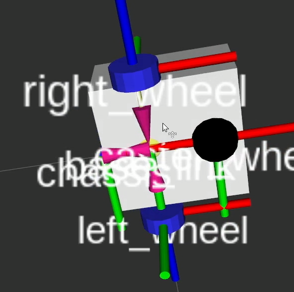
Caster wheel
Finally we need to add a caster wheel/s. The easiest way to do this is to simply add a frictionless sphere, connected to our chassis with the lowest point matching the base of the wheels. This isn't the most realistic physics simulation but is simpler to set up. Depending on the design, we sometimes want multiple caster wheels, but one will do for now. We'll cover the friction side of things in the next post.
1
Adding Collision and Inertia
Adding collision
Once we’ve got our core visual structure tweaked the way we want it, we need to add collision. The simplest way to do this is to copy-and-paste the geometry and origin from our <visual> tags into <collision> tags.
1
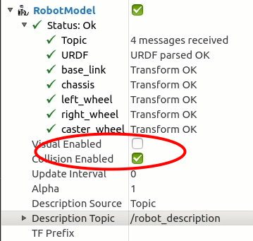
So go ahead and do this for all the links. To check if the collision geometry looks correct, in the RViz RobotModel display, we can untick "Visual Enabled" and tick "Collision Enabled" to see the collision geometry (it will use the colours from the visual geometry).
It's worth noting that this method isn’t really ideal - if we need to change any parameters (e.g. our wheels have a larger radius) we now have even more places to change them! Instead I strongly recommend you go through and use xacro properties to define your structure.
Adding inertia
The last things we need to add are our <inertia> tags. As noted in the URDF tutorial, calculating inertia values can sometimes be tricky, and it’s often easier to use macros. You can copy the entire inertial_macros.xacro file from the second tab and place it in your description/ directory. Then, near the top of your robot_core.xacro file (or robot.urdf.xacro) just under the opening <robot> tag, add the following line to include them.
1
Once that's in, go ahead and add the relevant macro to each link. Note that you'll need to specify an <origin> tag when using these macros. This should match the visual/collision origin, NOT the joint origin. So if the visual/inertial didn't have an origin, just specify it as all zeros. Again we have a box for the chassis, a cylinder for the drive wheels, and a sphere for the caster.
Here are my examples:
1
Extending on this
We now have a basic structure laid out that we can expand upon as we work on our design. As we add new aspects (sensors etc.) we can just keep creating and including more xacro files! This makes for a nicely modular, flexible, structured system.
The next step is to spawn our robot in Gazebo and drive it around with the keyboard. This post is long enough as it is, so the next part is in a separate post
Here are the key files we worked on:
1