Describing robots with URDF
Describing a Robot
When we create a robotic system, there may be many different software components that need to know about the physical characteristics of the robot. For consistency and simplicity, it is good to keep all of this information in one common location, where any code can reference it.
In ROS, we call this the robot description and the information is stored in a URDF (Unified Robot Description Format) file. We encountered URDF files briefly in the last tutorial and in this one we're going to dig deeper into how to write our own.
When we open up a complete URDF file it can look REALLY confusing - they are usually long, with a lot of symbols and words and it can be overwhelming. But if we take a moment to look more closely and break it down, we see that it is made up of a few simple structures repeated over and over. We'll take a look at these structures and then go through an example file.
This is a long one, so here are some shortcuts if you just need a quick answer!
Overall structure - Links and Joints
URDF describes a robot as a tree of links, that are connected by joints. The links represent the physical components of the robot, and the joints represent how one link moves relative to another link, effectively defining the location of the links in space.
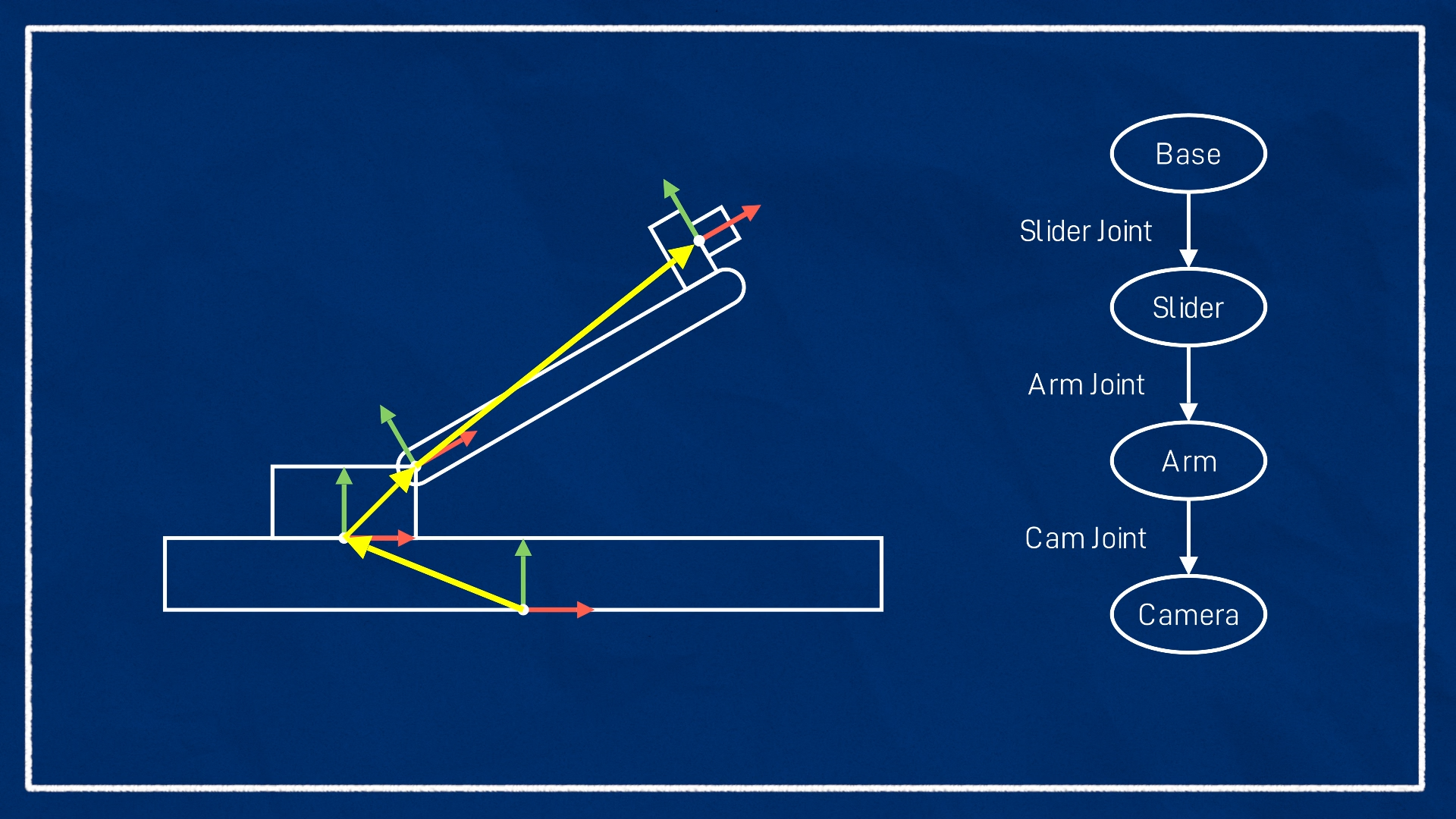
When we write our URDF file we need to figure out how to split the robot up sensibly into links (and joints). There are two main reasons we would designate a link/joint:
- A part of the robot is moving relative to another part (e.g. each segment of a robotic arm)
- A part that is not moving relative to another part, but it is convenient to have its own reference point and transform (a common example would be the location of a sensor such as a camera or lidar)
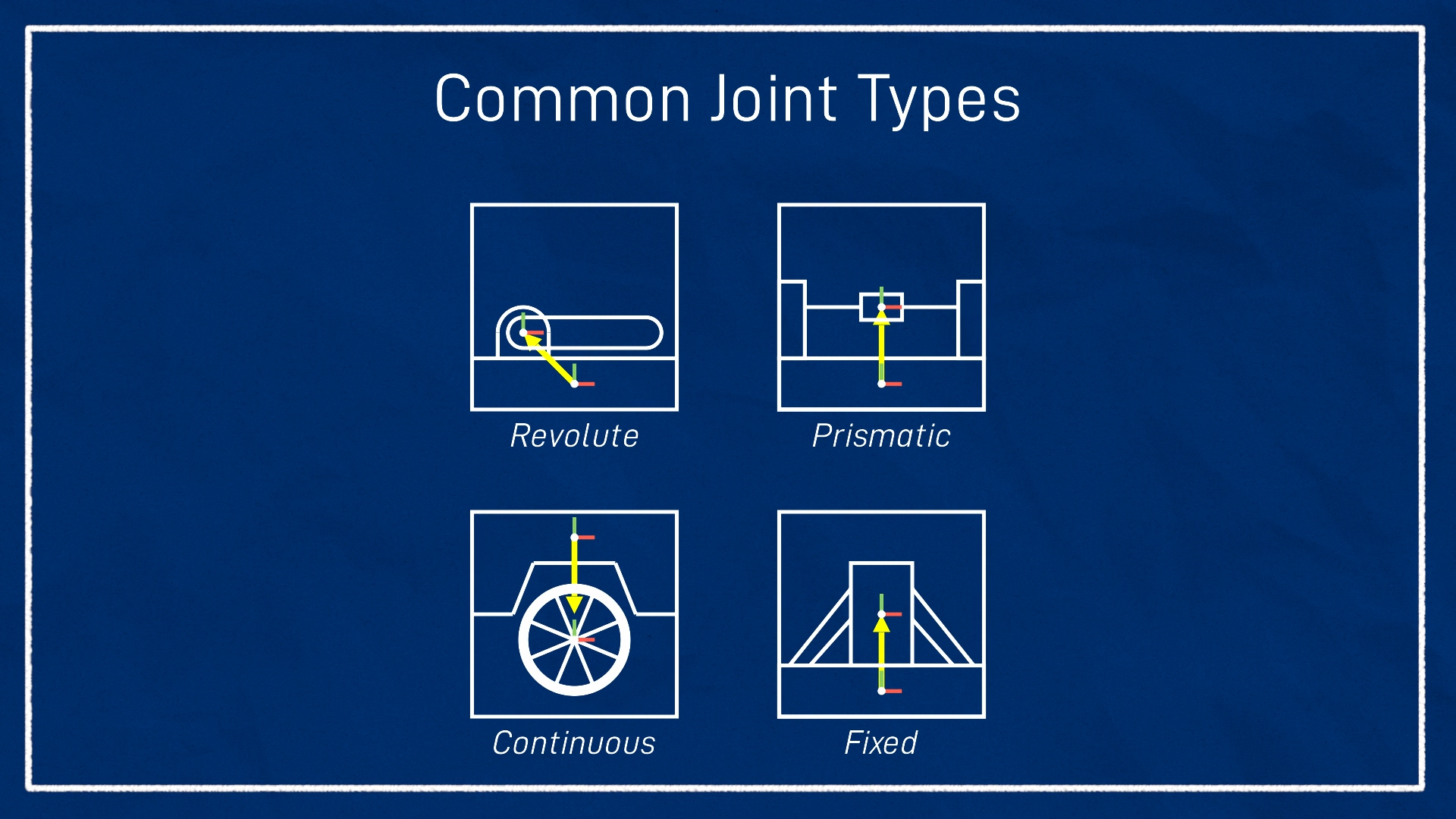
To cover these scenarios, when we define a joint (the connection between two links) we need to choose what type of joint it is. There are quite a few types, but the most common are:
- Revolute - A rotational motion, with minimum/maximum angle limits.
- Continuous - A rotational motion with no limit (e.g. a wheel).
- Prismatic - A linear sliding motion, with minimum/maximum position limits.
- Fixed - The child link is rigidly connected to the parent link. This is what we use for those "convenience" links.
To understand these a little better, let's dive into the actual format of URDF.
The URDF Syntax
URDF is based on XML, so everything is represented as a series of tags, which can be nested. There are many different tags we can use, but there are three main ones we need to know about.
The robot tag and XML declaration
A proper XML file should have an XML declaration/prolog in the first line, and then after that will be a single tag (called the root tag), which ALL the other tags live inside of. For a URDF file, this root tag will be the robot tag, and the only thing to note here for now is that we can set the name attribute which lets us (unsurprisingly) specify the name of our robot.
<?xml version="1.0"?>
<robot name="my_robot">
   ...
   all the rest of the tags
   ...
</robot>
Link tags
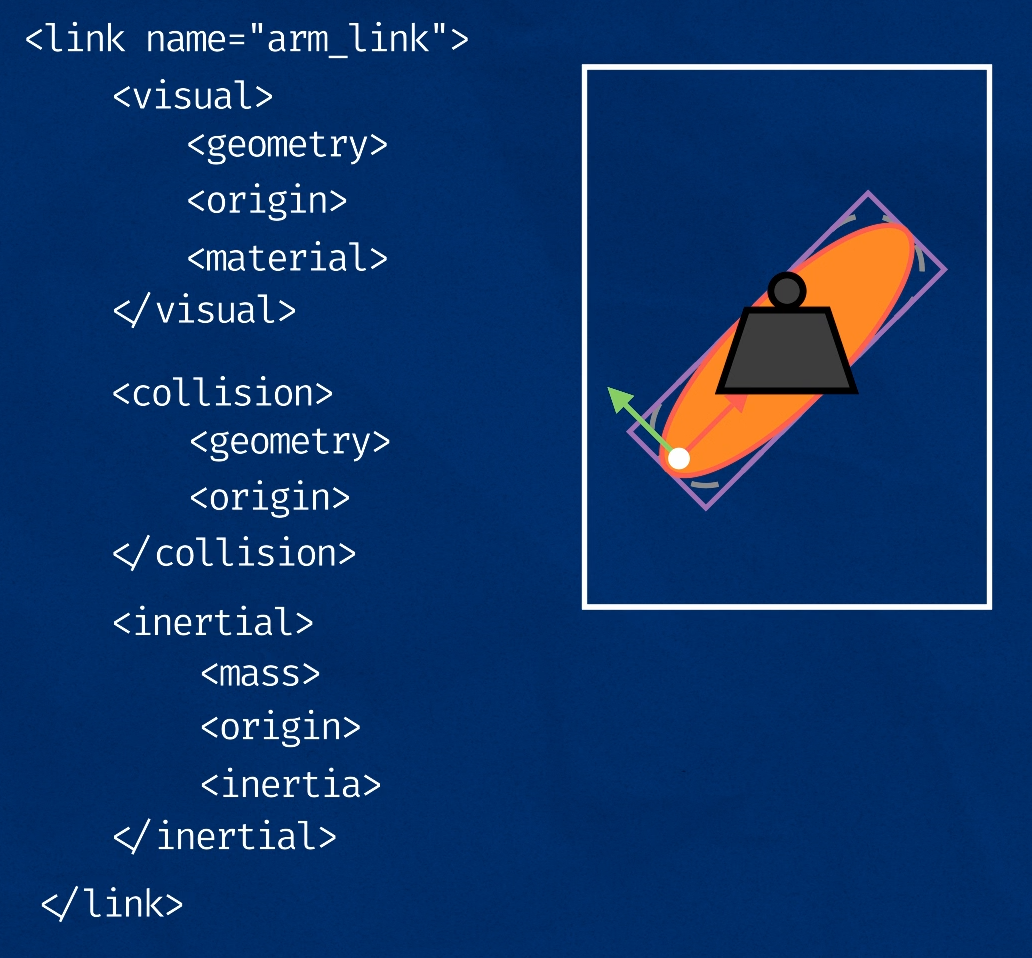
A link tag lets us firstly specify the name of a link, as well as some additional characteristics - the visual, collision, and inertial properties. These additional tags are generally optional, however they will be required for certain situations such as simulations (which we'll cover in a later tutorial).
- Visual - This is what we see in RViz and Gazebo. We can specify three aspects:
- Geometry -
box/cylinder/spherewith size parameters, or amesh - Origin - an offset for the geometry so it doesn't need to be centred around the link origin
- Material - Basically, the colour. We can specify the name of a declared material, or describe the colour directly. (Note that this will set the colour in RViz but not Gazebo, more on that in the next tutorial)
- Geometry -
- Collision - This is used for physics collision calculations. We can set the:
- Geometry and Origin - Same options as for visual. This will often be copy-pasted from the Visual tag, however we may want a simpler collision geometry (e.g. box instead of a mesh) for computational reasons.
- Inertial - This is also used for physics calculations, but determines how the link responds to forces. The inertial properties are:
- Mass - Mass of the link
- Origin - The centre of mass (a.k.a centre of gravity). This is the point the link could "balance" on (a slightly more confusing concept in 3D). For most simple cases this will just be the centre (same origin as visual/collision).
- Inertia - The rotational inertia matrix. This is probably the most confusing part of this section. It describes how the distribution of the mass will affect rotation. A list of the matrices for common shapes is available here. A fairly accurate simulation can be achieved by approximating our links as prisms, ellipsoids, or cylinders, however for most purposes a very rough guess will do. Also, don't get
inertialandinertiamixed up - the inertia matrix is just one part of the inertial properties.
Unless we are designing a very precise controller, there will be a fair bit of wiggle room in these parameters, especially the inertial ones. And remember, not every link needs all of these! Also, we can have multiple visual and collision tags for a single link if we want, so we can combine them to make more complex shapes.
This image shows the overall structure of a link tag, at the end of the tutorial we'll look in more detail at a working example.
Joint tags
Although we usually think of the robot as being made up of links, the joints are actually where all the detail is in terms of the robot's structure, as they define the link locations, and how they move relative to each other. This is similar to the previous tutorial on the TF system, where although we ultimately want to interact with frames, it's actually the transforms that define where the frames are, so it's important to get them right.
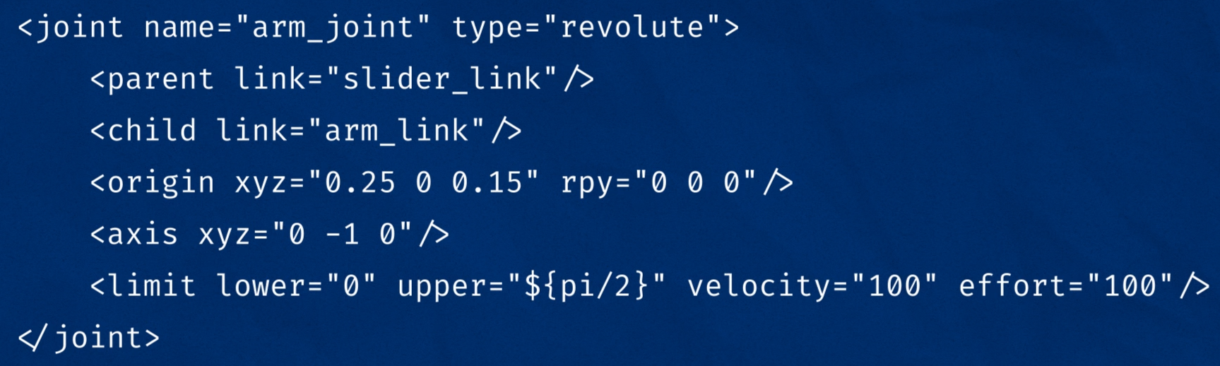
Each joint will need to have the following specified:
- Name - A name for the joint. If we don't have this, some things will still work, but other things won't. It's good to name them all just in case.
- Type - The joint type as mentioned earlier (the four most popular being
fixed,prismatic,revolute, andcontinuous). - Parent and child links - Which links this joint defines a relationship between
- Origin - The relationship between the two links, before any motion is applied
For a fixed joint these parameters will be sufficient, but for non-fixed joints we will usually want to specify some other characteristics. There are a few to choose from, but the two most common will be:
- Axis - Which axis to move along or around
- Limits - Physical actuation limits, which may be expected by other parts of the system. These can include:
- Upper and Lower position limits - in metres/radians
- Velocity limits - in m/s or rad/s
- Effort limits - in N or Nm
Below is a snippet of one of the joints that we'll look at in the example at the end.
Extra Tags
The robot, link, and joint tags are the main tags that make up a URDF file, but we're not just limited to these! There are a few other tags that are part of the URDF spec, but we can also add any other tags we like and they will just be ignored if not needed. Certain nodes will expect these extra tags and can make use of them.
Some common extra tags that you might come across are:
material- Allows us to give a "name" to a colour once, and then reuse that name in as many links as we likegazebo- Lets us specify certain parameters that are used in the Gazebo simulation environment (more on this in the next tutorial!)transmission- Provides more detail about how the joints are driven by physical actuators
Naming conventions
We need to name all our links to work with them, however it's good practice to name all our joints too. It's also good to keep consistency within your naming by following conventions, whether these are conventions set by ROS or just our own ones. Some examples of naming conventions we can follow are:
- Keeping our links/joints paired, and using the suffix
_linkand_joint(e.g.arm_linkandarm_joint) - Following the ROS conventions for humanoid robots
- Following the ROS conventions for mobile platforms
Introducing xacro
Before we look at an example of a URDF, it's worth learning about a tool ROS provides to make them easier to write, called xacro (short for XML macro). Xacro lets us manipulate the URDF files in various ways, but the two main ones we'll look at are splitting up code into multiple files, and avoiding duplicate code.
To enable the use of xacro in our file, all we need to do is make sure that our robot tag contains an extra bit as shown below. (You might notice that this particular robot tag doesn't have a name - more on that below!) It's easiest to just put this in every robot tag, so that you always have the option of using xacro if you want.
<robot xmlns:xacro="http://www.ros.org/wiki/xacro">
Then, whenever we want to actually use the URDF we need to run the xacro software over the files first, which will process them into a single, complete URDF "file" (temporary in memory). We saw this in the last tutorial, when we ran the robot_state_publisher. Even if we had multiple files going in, it would publish as one message to the robot_description topic. Typically we use a launch file like this one to do all this for us.

Using xacro to split up code
Being able to split up our URDF into multiple files is useful because they can become pretty large and unwieldy. Separating different components out makes it easier to find and change things, and also to quickly tell what has been changed when using version control software (like Git).
How we split up a URDF will depend on the individual developer and their hardware, but one example of the different files could be:
- Core robot (links and joints)
- List of materials (colours) to use for display
- Sensor links/joints and their corresponding Gazebo tags
- Macros (more on this in the next section)
So how does this work? To start off with, we will have one "main" file that represents the robot. As usual, its robot tag will have a name (as well as the xmlns:xacro bit mentioned above). Inside this file, we can "include" another file. It's sort of like the tags in the included file are copied-and-pasted into the main file. To include another file we use the xacro:include tag like this:
<xacro:include filename="first_file.xacro" />
For this to work, the included file has to be a bit special too. Like the main file, it will have a robot tag (with the xmlns:xacro bit), but we don't need to specify a name. Then, we can put whatever tags we want to include inside the robot tag.
Note, if we do specify a name then we can treat the included file as a standalone URDF, which may be useful sometimes.
We can include as many URDF/xacro files as we like (nested or in series), and we can use includes as well as normal tags.
Typically, the "main" URDF/xacro has the extension .urdf.xacro, but the "included" ones can vary a little. Sometimes they will just use .xacro, sometimes they will also be .urdf.xacro, and sometimes they will have other extensions.
Using xacro to avoid duplicate code
An important principle in programming is DRY (Don't Repeat Yourself). Having the same procedure or information in multiple places is a problem for a few reasons, including:
- The more times you need to write it, the more likely you are to do one incorrectly
- When you need to change a process or piece of data, it's a pain to have to do it in multiple locations
- If you don't remember to change all of the locations, you'll end up with an inconsistent system, which can have disastrous consequences (e.g. one part of the code thinks 100% speed is 0.1m/s and requests 100% speed. If the motor controller thinks 100% speed is actually 10m/s, you'll soon have a collision on your hands!)
Some of the ways Xacro helps us to simplify our URDF, and avoid repeating code or making mistakes are:
Properties
We can declare a property to be some constant and then use it later on.
<xacro:property name="arm_radius" value="0.5" />`
...
<cylinder radius="${arm_radius}" length="7" />
Mathematical Operations
We can use mathematical constants and operators inside attributes, which can also be combined with properties.
<cylinder length="${4*arm_radius + pi}">
Macros
We can create a macro, which is a template that can be reused later, and varies based on parameters. The example below shows a macro to handle the inertial parameters for a box.
<xacro:macro name="inertial_box" params="mass x y z *origin">
    <inertial>
        <xacro:insert_block name="origin"/>
        <mass value="${mass}" />
        <inertia ixx="${(1/12) * mass * (y*y+z*z)}" ixy="0.0" ixz="0.0"
                iyy="${(1/12) * mass * (x*x+z*z)}" iyz="0.0"
                izz="${(1/12) * mass * (x*x+y*y)}" />
    </inertial>
</xacro:macro>

...then ...

<xacro:inertial_box mass="12" x="2" y="3" z="4">
    <origin xyz="0 2 4" rpy="0 0 0"/>
</xacro:inertial_box>

... will expand to ...

<inertial>
    <origin xyz="0 2 4" rpy="0 0 0"/>
    <mass value="12" />
    <inertia ixx="25" ixy="0.0" ixz="0.0"
            iyy="20" iyz="0.0"
            izz="13" />
</inertial>
Full Example
Below is an example of a URDF file and an included file. To run this yourself, visit this repo.
Main File:
Include File:
Up Next
Now that we know how to write our own URDF files, we're ready to start using Gazebo, the robot simulator. In the next tutorial we'll see how we can use Gazebo to simulate robots in an environment.
References
The ROS wiki has some good documentation for this stuff. In particular, check out the following:
- http://wiki.ros.org/urdf/XML
- https://wiki.ros.org/urdf/XML/link
- http://wiki.ros.org/urdf/XML/joint
- https://wiki.ros.org/xacro